Tri-R Technologies
TR-4
BUILDER'S
MANUAL
This Builder's Manual is NOT the official manual
as published by TRI-R Technologies.
FUSELAGE
Quick Links to Wing Assembly Sub-Sections:
SPAR
PREPARATION
LEVELING
AND FIXTURING
SPREADER
STICKS
TEMPORARY
FITTING OF THE FUSELAGE TOP
FIREWALL
FIREWALL
FRONT FACE
ADDED REINFORCING IN FIREWALL AREA
STATION
139.5 BULK HEAD
STATION
180.5 BULKHEAD
MAIN
SPAR AND OUTBOARD SPAR PRE ASSEMBLY
REAR
SPAR
MAIN SPAR LOCATION AND INSTALLATION
POSITIONING
SPAR
MOUNTING LAMINATIONS
MAIN
GEAR BOX REINFORCEMENT
SEAT
FRONT BULKHEAD & CONTROL MOUNT
FUSELAGE
BELTLINE
CONDUITS
FRONT SEAT BACK ASSEMBLY
REAR
SEAT BACK INSTALLATION
CONTROL
CONSOLE - FRONT SEAT AREA
ELEVATOR
IDLER BELL
CRANK
SEAT BOTTOM ASSEMBLY
FRONT
SEAT
REAR
SEATS
FRONT
FLOOR ASSEMBLY
STICK
LINKAGE ASSEMBLY
FLAP
HANDLE ASSEMBLY BRACKET
AILERON
IDLER INSTALLATION
FLAP ACTUATION TORQUE TUBE INSTALLATION
RUDDER
IDLER LEVER INSTALLATION
HORIZONTAL
STABILIZER
INSTALL
RUDDER POST
ELEVATOR AND PUSH/PULL ROD
INSTALLATION
RUDDER CABLE ROUTING AND
INSTALLATION
MAIN
GEAR INSTALLATION
BRAKE
LINE INSTALLATION
FIN
RIGHT HALF INSTALLATION
INSTALL
LEFT FIN HALF
HANGING
RUDDER
INSTALLATION
OF FUSELAGE TOP
BAGGAGE
AREA BACK PANEL
DOOR
PREPARATION
WINDOW
INSTALLATION
DOOR
LATCH ASSEMBLY
MOUNT
DOORS
LATCH
PLATE INSTALLATION
AIR
STRUT INSTALLATION
REAR
WINDOWS
INSTRUMENT
PANEL
WINDSHIELD
FRONT FLOOR
ASSEMBLY
-
Temporarily install some cushions in the seat area, securely support the
fuselage assembly and sit in place to verify the location where you will
be installing the rudder pedal assembly on the front floor section.
About plus or minus 3 inches of adjustment can still be made in rigging after
the rudder block positions are set. The floor panel itself is to be installed
with the outer ears touching the back of the firewall.
-
Check to be sure that there is 1.5 inch clearance between the upper surface
of the floor panel and the bolt hole position for the engine mount. If this
value is not attained reduce the forward outer width of the floor panel slightly
to lower the panel.
In general the rudder pedal system should be located as close to the fire
wall as the linkage will permit. However, if the intended primary pilot has
relatively short legs, it may be beneficial to move this pedal assembly back
closer to the seat, and adjust the location of the hard points for the rudder
pedal pivot blocks accordingly.
The front floor assembly is fabricated from three pieces of the two ply prepreg
panel material supplied. The basic floor panel, are cut out and fitted to
the fuselage inner contour as shown figure XXX.
-
Before the assembly of these pieces, "hard points" for the rudder pedal assembly
are added to the basic floor panel, located as shown in the Figure XXX enclosed
and with any adjustments in location dictated by the "sit test".
The configuration shown for the rudder pedal mounting inserts are individual
plywood blocks inserted into the floor for a total of four hard points for
the four mounting blocks. An alternate configuration is an enlarged rectangle
which will encompass all four of the center holes (both center rudder pedal
mounting blocks) at some small penalty in weight .
-
Cut out the three (or four) pieces of the 1/4 inch plywood and locate them
on the bottom surface of the floor panel in the positions called out in the
figure XXX (remember that you are installing the hard points on the back
side, so turn the floor over).
-
Use the cut pieces as a cutting guide, and cut through the bottom skin of
the panel. Figure XXX shows the recommended standard location, revise if
required to position the pedals to your requirements (as previously defined
in your sit test).
-
-
Remove the skin and the core material, and clean the exposed inner surface
of the top skin in preparation for bonding.
-
Bond the inserts into there cavities, and fill any gaps between the insert
and the core with a relatively dry FLOX/MICRO paste. Cover these inserts
with two ply BID, with minimum 1 inch over lap over the existing bottom skin
around the insert.
-
Fabricate the four rudder pedal assembly mounting blocks per the figure XXX.
Two of these blocks have a 7/8 inch lower segment, and two have a 1 inch
high lower segment (ref. Figure XXX). The shorter (7/8 inch) rudder blocks
will be used in the locations where the blocks are to be installed on the
top of the 1/8th inch thick aluminum angle used for the brake cylinder mounting
bracket. The supplied material for all four blocks is the 1/2 inch thick
phenolic contained in the kit (other suitable bearing material such as nylon
can be substituted). The two center blocks may require some reduction in
the 1/2 inch thickness to provide clearance for the flanges on the pedal
tubing, to allow the rudder pedals to rotate freely. This is most easily
accomplished with a belt sander.
-
The bolts mounting the two blocks on the left (pilot side), will also mount
the brackets for the brake master cylinders. Fabricate these brackets from
1/8 in. thick aluminum angle supplied with the kit. The smaller bracket will
be installed on the left side for the left toe brake, and the larger (longer)
angle will be used for the right toe brake. Use figure XXX to fabricate the
brackets, using the respective rudder mounting blocks as drill jigs to assure
proper fit through the bolt holes.
-
Position the blocks on the floor panel (with the hard points installed),
using either the rudder assemblies, and use the blocks as drill jigs for
the eight attach bolts (#10 - 32 hex head screws about 2 1/4 inches long
- AN3-22A).
-
Use the attach bolts to hold the nut plates in position, and drill for the
3/32 in. rivets which will be used to attach the nut plates (K 1000 - 3).
Rivet the nut plates in position as shown in the preceding sketch.
-
Temporarily install the bearing blocks for the rudder pedal assembly, with
the brake cylinder mounting angles on the pilot side, and the pedal assembly
for fit and functional testing.
A "U" shaped cutout at least one inch square, must be provided on both the
front and rear close out panels of the floorboard assembly. These cutouts
allow for the passage of the fuel, brake, and other lines or wires between
the spar area and the fire wall area.
-
Attach the end panels to the floorboard assembly with two inch wide two ply
BID at the corners, and fit the assembly to the fuselage inner surface.
-
As mentioned earlier, the location of the rudder pedals shown in the drawing
is the nominal value used in the prototype. If the anticipated pilots are
taller, or shorter, the location of the rudder pedals can be adjusted to
provide the desired distance between seats and the nominal rudder pedal location.
The floor panel however, is to be installed with the front, side "ears" up
against the fire wall as shown in figure XXX. When located in this position,
bond the floor assembly into place with two inch wide two ply BID tape. Roughen
the surface of the fiberglass on the firewall and the plywood gusset to prepare
these surfaces for bonding. Bond the "ears" to the firewall with a two ply
pattern with double overlap on the firewall at the engine mount location.
This will add four plies to the lower engine mount pads.
STICK LINKAGE
ASSEMBLY
-
The stick linkage assembly process is started by temporarily installing the
stick assembly mounting brackets (KS -29) to the control cross over (KS-30)
at the two pivot brackets welded to the bottom of KS-30).
-
Position the control cross over assembly up against the rear face of the
front seat forward bulkhead, with the pivot line at WL -11.75 (11 3/4") and
the stick assembly centered in the fuselage (caution - the elevator push
rod clevis is not centered on the control cross over assembly).
-
Using the mounting brackets as templates, mark and drill, the two 3/16 in.
dia. bolt holes through the bulkhead hard points.
-
Bolt the two stick pivot brackets to the aft face of this bulkhead, using
the previously drilled holes, using four hex head #10- 32 bolts about 3/4
inch long (AN 3-SA), and associated nuts and washers supplied in the kit.
FLAP HANDLE ASSEMBLY
BRACKET
This would also be a good time to install the bracket for the flap actuation
linkage and the lever sector plate assembly (KS- 26). Use the flap sector
stampings (two flat plates with the flap position notches) to mock up the
vertical location for this bracket by assembling the flap handle assembly.
-
The recommended position is to mount this bracket on a 1/4 inch plywood spacer
and center the upper hole in the mounting bracket on the upper edge of the
bulkhead (this hole is not used in mounting). With the control crossover
assembly installed to it's mounting brackets and the flap handle assembly
held in place, cycle this assembly to determine clearance with the flap sector
bracket and the sectors.
-
Use the lower hole as a jig and drill the lower bolt hole in the front seat
front bulkhead for mounting.
-
Mount the bracket with the one hex head #10-32 bolt about 1 in. long, AN3-7A
or similar, and required nut and washer .
-
Select the flap sector sides, and the flap handle assembly and temporarily
assemble to the just mounted bracket.
-
Locate and drill the bottom mounting hole through the side of the console
4 1/4 inches aft of the bulkhead aft surface. Before doing so, hold the assembly
in place and fit the console cover over the assembly and make sure there
is not any interference with the flap handle or sector sides.
-
Locate the top hole on the side panel using the sector side panel hole with
the assembly held in place.
-
Using the supplied nuts, bolts, washers, and spacers (the spacers are cut
from the 5" steel tube supplied). Install the flap actuation assembly of
the handle and the two sector panels. The push rods for these areas will
be installed at a later step.
AILERON IDLER
INSTALLATION
-
The aileron idler, two pieces, left and right are to be fabricated from a
section of the 1 by 1 inch .125 wall aluminum channel furnished in the kit
using figure XXX. Fabrication should be easily accomplished using simple
hand tools such as hacksaw, files, and drill .
-
Locate the pivot point for this link by positioning a KS-3 bracket face against
the aft surface of the seat front bulkhead, base against the inner fuselage
wall with the hole 2 5/8 inches below the top of the seat front bulkhead
(see sketch). Mark the hole location in the seat front bulkhead.
-
Insert a 2 in. square hard point in this position (if this was not accomplished
at an earlier time.
-
Space the KS-3 bracket with the idler link and two washers and mark the mounting
holes in the fuselage wall.
-
Insert a hard point on the inner wall to make a flat spot for the bracket
(the insert piece to be about 1/16 inch less tall than the span of the bracket
but 2 inches wide. Close with 2 ply BID with at least 1/2 inch overlap all
around.
-
Drill holes and mount KS-3 bracket with counter sunk #10-32 bolts.
-
Using the idler and bracket, locate the position of the hole to be drilled
into the 31 bulkhead hard point. Drill a ¼" hole.
-
Install the idler with a 1/4 inch bolt (AN4-16 or similar) and castleated
nut and washers .
-
Assemble the stick to idler push rod with two rod end assemblies and a section
of ¼" inch threaded rod and the required nuts. Rig the length of this
rod to set the indicated idler holes in a vertical plane when the stick is
neutralized. (see figure XXX).
Repeat this procedure on the other side of the fuselage.
FLAP
ACTUATION TORQUE TUBE INSTALLATION
The flap actuation torque tube is a one piece assembly and it mounts on the
aft face of the wing rear carry through spar.
-
Mount one of the three torque tube mounting brackets (CS-23) at each end
of the spar, located 3/8 inch below the top edge, and one inch in from the
end. Mount these with only the top bolt at this time such that they can align
with the assembly. The bolts are #10-32 flat head counter sunk bolts (MS-24
694-S56 ), counter sink the front face of the spar such that the bolt head
does not protrude above the surface (the wing rear spar surface will be bolted
up tight to this surface) .
-
Using the bracket as a guide, mark and cut at least a 1.25 inch dia. hole
(this hole will be elongated due to the fuse’ angle), with a hole saw
or Dremel in the fuselage side, to allow the tube to protrude through the
fuselage surface and operate freely without binding. Repeat this step on
the opposite side.
-
Prepare the torque tube assembly by installing the actuation arm (CS-32)
on each end of the torque tube. These must be installed as precisely parallel
as possible to avoid dangerous eccentric flight loads when the flaps are
deployed. The recommended way to accomplish this is to work on a flat level
surface and install first one actuation arm at one end, drilling through
both the arm and the tube with a 3/16th in. dia. 2 places as close together
as 2 #10-32 hex head bolts can be spaced. Install each bolt as soon as the
hole is drilled.
-
Align the other arm using the flat surface as a guide, and drill and install
the bolts in the same manner. Mark the actuation tube and the arms such that
they will not be switched when reassembled. Remove the right side arm to
prepare for the following steps.
-
Slip the torque tube through the mounting bracket and fuselage hole on the
left side. Slip the remaining mounting bracket and the flap actuation input
lever arm (in this order), onto the inboard end of the torque tube, and pass
the end of the tube through the other fuselage wall, and the hanger bracket
on the far side.
-
Position the actuation arm on the torque tube assembly, such that it is in
line with the flap actuation lever assembly in the center console (not centered
in the console but aligned to the left side to permit room for the elevator
push pull rod assembly on the right side).
-
Locate the loose (center) flap hanger bracket adjacent to the actuation arm,
and drill the top mounting hole for the middle mounting bracket (this bracket
location should be near the airplane centerline if the assembly is proper).
This center mounting bracket may be mounted with hex head #10-32 bolts since
the flush surface is not required, and access will be better for a wrench
than a screwdriver.
-
Center the actuation tube in the aircraft, and assure that sufficient free
end is available at each end for mounting the flap driver arms (the torque
tube should be even with the ends of the spar).
-
Level the flap actuation arms that are at the ends of the torque tube and
secure in this positon. Set the center input actuation arm vertical, and
drill through the flap actuator arm, and the tube for two #10-32 bolts. Space
the bolts just enough to provide wrench access.
-
Install the bolts pointing aft when the actuation arm is vertical, to permit
free rotation during flap actuation.
-
With the torque tube assembled, pivot it several times to clear up any
interference and binding, and locate and drill for the second mounting bolt
in each bearing bracket. The outer bolts are also the flat head #10-32
countersunk bolts, installed as before, and the second mounting bolt for
the center bracket is another hex head #10-32..
-
Select the flap actuator push rod assembly ( part CS- 24 ) from the included
parts, and trim the open tube end such that the nominal length of the assembly
will hold the torque tube actuation arm vertical in the flap retracted (forward)
lever position.
-
Complete this assembly by installing the AN 490HT8P adapter (rivet in place)
and MW-3M8/F34-14 rod end, and install in place. Cycle the assembly through
the flap positions to assure free movement and no interference with structure
or other control components.
RUDDER IDLER
LEVER INSTALLATION
This aircraft uses a rudder idler arm mounted on the station 180.5 bulkhead,
connected to the rudder cables, and transferring actuation force to the rudder
push/pull actuator "rod". This cleans up the aircraft aerodynamically by
eliminating the external cables to the usual rudder actuator bar.
-
This idler arm is fabricated from a section of the 1 inch aluminum "C" channel
section furnished in the kit. Reference the figure X-10 for dimensions and
configuration of this idler. Two options are provided for the making of this
idler, one without outer bushings and one with. It is suggested that bushings
be used wherever there is a chance of the bolt turning in the bolt hole.
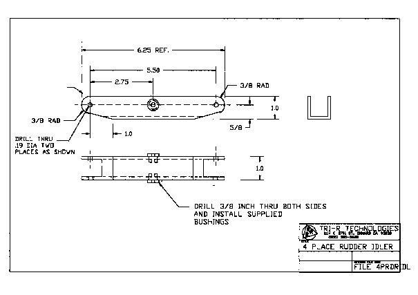
Figure -10, Rudder Idler Arm.
-
This idler rotates on the supplied hat shaped oilite bushings provided. It
is best to ream these holes to 3/8" for the best fit of the oilight bushings.
If the bushings are not a tight fit in the hole, a drop of epoxy or one of
the "Locktite" compounds will secure them in place.
-
Assemble the idler to the two support angles (KIS -3 ) with a #10 bolt with
a washer between all rubbing surfaces as shown, and secured with a castleated
nut to provide freedom of movement with a minimum of clearance, as shown
in figure x-x
-
Position the assembly on the 180.5 bulkhead at the leading edge of the horizontal
stabilizer (as shown in figure XXX). Drill and mount with #10 bolts and lock
nuts. Drill these holes square to each other so binding will not occur.
-
Locate and cut holes in the bulkhead to allow full movement of the idler
arm and allow installation of the rudder push pull tube. Verify operation
and fill the edge of the holes with dry MICRO.
-
The correct geometry will be assured if the rudder cables are crossed forward
of this idler, and the push rod installed on the left side in a straight
line to the rudder actuation arm.
-
There is sufficient room in this idler link to install both the rod end and
the cable thimble. See figure xx. Use sufficient washers to avoid interference
between the two, and a large number of washers on the other end to keep the
cable thimble roughly centered.