Tri-R Technologies
TR-4
BUILDER'S
MANUAL
This Builder's Manual is NOT the official manual
as published by TRI-R Technologies.
FUSELAGE
Quick Links to Wing Assembly Sub-Sections:
SPAR
PREPARATION
LEVELING
AND FIXTURING
SPREADER
STICKS
TEMPORARY
FITTING OF THE FUSELAGE TOP
FIREWALL
FIREWALL
FRONT FACE
ADDED REINFORCING IN FIREWALL AREA
STATION
139.5 BULK HEAD
STATION
180.5 BULKHEAD
MAIN
SPAR AND OUTBOARD SPAR PRE ASSEMBLY
REAR
SPAR
MAIN SPAR LOCATION AND INSTALLATION
POSITIONING
SPAR
MOUNTING LAMINATIONS
MAIN
GEAR BOX REINFORCEMENT
SEAT
FRONT BULKHEAD & CONTROL MOUNT
FUSELAGE
BELTLINE
CONDUITS
FRONT SEAT BACK ASSEMBLY
REAR
SEAT BACK INSTALLATION
CONTROL
CONSOLE - FRONT SEAT AREA
ELEVATOR
IDLER BELL
CRANK
SEAT BOTTOM ASSEMBLY
FRONT
SEAT
REAR
SEATS
FRONT
FLOOR ASSEMBLY
STICK
LINKAGE ASSEMBLY
FLAP
HANDLE ASSEMBLY BRACKET
AILERON
IDLER INSTALLATION
FLAP ACTUATION TORQUE TUBE INSTALLATION
RUDDER
IDLER LEVER INSTALLATION
HORIZONTAL
STABILIZER
INSTALL
RUDDER POST
ELEVATOR AND PUSH/PULL ROD
INSTALLATION
RUDDER CABLE ROUTING AND
INSTALLATION
MAIN
GEAR INSTALLATION
BRAKE
LINE INSTALLATION
FIN
RIGHT HALF INSTALLATION
INSTALL
LEFT FIN HALF
HANGING
RUDDER
INSTALLATION
OF FUSELAGE TOP
BAGGAGE
AREA BACK PANEL
DOOR
PREPARATION
WINDOW
INSTALLATION
DOOR
LATCH ASSEMBLY
MOUNT
DOORS
LATCH
PLATE INSTALLATION
AIR
STRUT INSTALLATION
REAR
WINDOWS
INSTRUMENT
PANEL
WINDSHIELD
STATION 139.5 BULK
HEAD
The mid tail cone bulkhead is located at station 139.5. This bulkhead is
located at the joint between the fuselage top section and the right and left
hand fin halves. This bulk head is cut from a section of the two ply prepreg
panel that has the outline of this part drawn on the panel at the factory.
-
Cut this part out carefully since the station 180.5 bulkhead is outlined
in the center, and will be cut out from this part. Use a fine tooth saber
saw blade or similar tool for this operation. The outline provided is on
the generous side so some trimming or block sanding may be required to fit
it to the two fuselage halves.
-
Cut out the center section containing the 180.5 bulkhead and set it aside
for the next step. Carefully install and remove the fuselage top half for
fitting these components.
-
The 139.5 station location is to the front face of this bulkhead panel. Remember
that the station 0-0 reference is at the ""joggle"" where you lined up the
firewall, reference these locations from that point. Test fit the bulkhead
into the proper position, trimming as required for a good fitted joint, and
prepare both the bulkhead surface and the inner fuselage surface for bonding.
Mark the upper fuselage edge position (Water line 0.0) on the bulkhead.
-
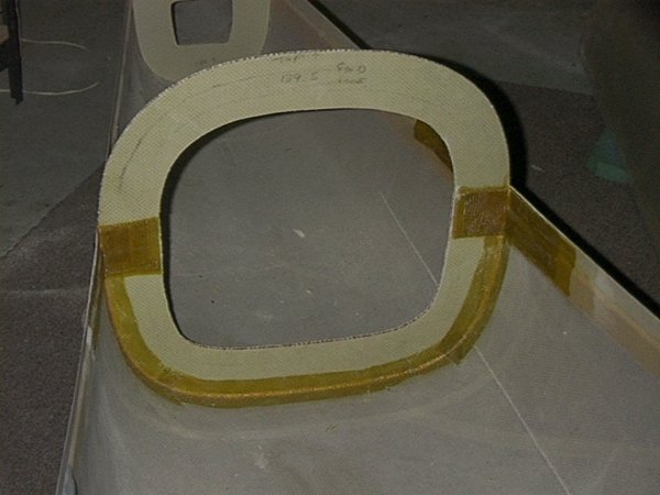
Fit the bulkhead and align it carefully. Secure in place to the bottom fuselage
half with some dabs of five minute epoxy.
-
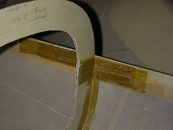
When it is secure enough to work with, bond it to the lower section with
two layers of two inch BID tape on both front and back faces. In this location,
as other places where there is an inside angle joint, fill the corner with
a small radius MICRO/FLOX fillet and wet out the bonding areas with brushed
on epoxy. Provide a uniform one inch overlap on each part.
-
Insert the 1" by 1" plywood insert at belt the line as shown in the drawing
with a 2 by 6 inch, 4 ply prelam BID front and aft of these plywood inserts.
These are "hard points" for the shoulder harness for the rear seat
passengers.
Image 126-127: Station 139.5
 |
|
 |
STATION 180.5
BULKHEAD
The aft tail-cone bulk head is located at station 180.5. This bulk head is
located at the leading edge of the horizontal stabilizer. The bulkhead is
cut from the pre-marked two ply prepreg panel (inside the opening of station
139.5 bulkhead).
-
This part should be cut out carefully with a fine tooth saw and located with
the front face at station 180.5 . It may need to be trimmed for proper fit
and should then be tacked into place with five minute epoxy. This bulkhead
will have to be removed temporarily during the installation of the horizontal
stabilizer, so use a minimum amount of the five minute epoxy in "tacking"
it into place.
This bulkhead will also require a hard point for mounting the rudder idler
bell crank as follows:
-
Cut a 3 inch square of the 1/4 plywood, and cut away an equal size skin (one
skin only) on the aft face of this bulkhead as shown in figure XXX.
-
Inset the plywood with MICRO slurry, and cover with 4 plies of BID large
enough for a full overlap around the patch and extending outwards to the
edge of the bulkhead as shown in the sketch (this hard point supports the
rudder idler which can have high loads applied at times by the pilot's feet).
-
Mock up the idler assembly with the two KIS-3 brackets and locate the mounting
holes on the ply insert.
-
Lightly "tack" this bulkhead in to place at the stated location - it will
be removed and permanently installed during the horizontal stabilizer
installation.

