 |
Tri-R Technologies TR-4
BUILDER'S MANUAL
This Builder's Manual is NOT the official manual as published by TRI-R Technologies.
Introduction
Quick Links to Introduction Sub-Sections:
HEALTH
AND SAFETY IN HANDLING COMPOSITE MATERIALS
COMPOSITE
TERMS AND PROCEDURES
REMOVING
PEEL PLY
BID
PREPARATION
FOR BONDING
MOLDED
SURFACES
PEEL
PLY SURFACES
MICRO and
FLOX
BONDING
AND LAMINATING TO FOAM
GREEN
TRIMMING
CAUTIONS
DIMENSIONS
AND STATIONS SYSTEM
STATIONS
BUTT
LINE
WATERLINE
SHOP
& TOOLS
TOOLS
& EQUIPMENT
TYPICAL
HAND
TOOLS
TYPICAL POWER TOOLS
SUGGESTIONS
EPOXY
SCALES
SCALES
DIRECTIONS FOR USE
INTRODUCTION
Congratulations upon your selection of KIS as a construction project for
your own personal Kit Plane. If you have constructed other composite aircraft
in the past you will be pleasantly surprised at the simplicity and ease with
which this project will progress. If this is your first construction project,
please pay particular attention to all phases of the instructions and you
will also be guided to the satisfying completion of this excellent aircraft.
The underlying theme in this entire design approach is for simplicity in
both construction and operation of the completed aircraft. This manual provides
detailed step-by-step instructions for the KIS aircraft assembly. However
in the basic instructions in each section, assume a certain degree of familiarity
and experience with composite construction materials. The introductory chapter
will define many of the terms used throughout this manual. If you do not
have any previous experience, refer to other texts, and possibly do some
small trial projects with composite construction.
IF DURING CONSTRUCTION YOU HAVE ANY QUESTIONS OR DOUBT ABOUT A CONSTRUCTION PROCEDURE, DO NOT CONTINUE UNTIL YOU HAVE OBTAINED THE REQUIRED INFORMATION OR SKILL TO COMPLETE THAT PROCEDURE PROPERLY. IF YOU ARE NOT KNOWLEDGEABLE ABOUT FIBERGLAS CONSTRUCTION TECHNIQUES, PLEASE REVIEW SOME OF THE REFERENCED SOURCES TO OBTAIN THAT KNOWLEDGE BEFORE STARTING CONSTRUCTION. IT WOULD ALSO BE VERY USEFUL TO ENLIST THE AID OF SOMEONE WITH PRIOR EXPERIENCE TO ASSIST YOU AND PROVIDE TRAINING IN THESE PROCEDURES. CHANGES TO THE AIRCRAFT DESIGN OR SPECIFIED CONSTRUCTION PROCEDURES MUST NOT BE MADE WITHOUT PRIOR APPROVAL OF TRI -R TECHNOLOGIES STAFF. UNAUTHORIZED CHANGES MAY CREATE A DANGEROUS CONDITION IMPACTING AIRCRAFT SAFETY AND/OR STRUCTURAL INTEGRITY. FAILURE TO COMPLY WITH THESE WARNINGS AND/OR OTHER INSTRUCTIONS AND CAUTIONS CONTAINED IN THIS MANUAL MAY RESULT IN AN UNSAFE AIRCRAFT WITH INCREASED POTENTIAL FOR INJURY OR POSSIBLE FATALITIES.
PROCEDURES
HEALTH AND SAFETY IN HANDLING COMPOSITE MATERIALS
The materials selected for this kit are the safest, least toxic, applicable
materials for this type of construction, but several simple precautions and
operating procedures should be applied for your personal well being, and
satisfactory completion of the kit. As a general case, the materials in this
kit are no more hazardous than many of the fluids and products that one handles
in everyday life. Examples of items of similar risk are gasoline, paint and
thinners, and many household cleaning products. Just as with these substances,
several safety precautions should be employed to prevent illness, physical
injury, and possible adverse allergic reactions.
Gloves and other protective equipment are recommended for handling any of
the liquid or paste resins and adhesives. Disposable surgical gloves are
often used for this type work, but they are very fragile, and easily torn
on the glass fibers, or other sharp edges. Some of the heavier kitchen type
non porous gloves may prove more durable, and easier to use.
Breathing protection should be used in cutting, grinding, or sanding any
of the structural materials, or when handling any of the powder or fibrous
materials. Work in well ventilated areas, and clean up hands, and all spilled
materials, particularly before handling any foodstuffs, or tobacco products,
or any other means by which the materials may be ingested or gotten into
the eyes, nose, or mouth.
Smoking or eating in the composite shop area is to be vigorously discouraged.
Carefully read the instructions and cautions on each new product as you encounter
it during your construction progress. Quickly employ the listed medical cautions
and recommended procedures, if any of these products are ingested, or are
providing any undue levels of irritation or other reactions.
COMPOSITE TERMS AND PROCEDURES
Many of the same techniques and procedures apply to numerous assembly steps, so some of the more common will be covered in detail in this section to avoid cumbersome repeating through all of the individual sections. One of our staff has suggested that a most important procedure is to put a set of cheap seat covers on your car. This is probably good advice, and relates to the fact that you will be dealing with sticky messy materials that are even more durable than paint, so keep in mind the hazard of damaging your clothes, your car seats, or what would be worse - YOUR SPOUSE'S FURNITURE!!
Most of the molded parts will be covered on the back side, with sheets of material called "peel ply'. This is a cloth material which resists bonding to the resin surface and allows surplus resin to be squeezed out of the part during pressure curing,. This material is left in place after fabrication since it provides protection to the part from some physical damage and contamination. This material must be removed prior to assembly, but it is suggested that this be one of the final steps just before the "dry assembly" and the mixing of resins and adhesives, to maximize the protection provided.
The peel ply usually sticks out on some place of the part where it will look like white cloth. Where it is adhered to the part, the epoxy may give it a transparent appearance. The material is basically removed by pulling it by hand. Frequently it will tear before clearing the entire area, and a new corner will have to be lifted carefully with a utility knife ( a wood chisel also works well for this ). The white cotton strips running irregularly over the surface of the part must also be removed with the peel ply.
IT IS ESPECIALLY IMPORTANT THAT ALL TRACES OF PEEL PLY BE REMOVED FROM THE BONDING AREAS, SINCE IT WILL TOTALLY VOID BOND STRUCTURAL INTEGRITY LEADING TO POSSIBLE STRUCTURAL FAILURE.
BID is a generally used contraction in composite construction and stands for "BI Directional" glass cloth. This is cloth woven in a manner similar to what you are used to seeing in most fabrics where there about equal numbers and sizes of strands in the longitudinal direction as in the crosswise direction . This is to differentiate between those composite fiber weaves known as unidirectional (UNI) where the primary strength is in the longitudinal direction, and only enough crosswise fibers are used to hold the material together for handling. In this kit we will only be dealing with BID for the assembly steps (in the premolded factory parts UNI is used in many places to maximize required strength but only BID is used for the final assembly steps).
The appropriate BID fabric is provided in the kit (and if you damage some, or otherwise run short please contact Tri-R for proper replacement. Do not substitute with unproved materials. Most of the uses will call for bias cut strips, so it will be useful to set up the supplied cloth on a cutting table and cut out a supply of these bias cut strips. A bias cut strip is cut diagonally across the length of your fabric material at 45 degrees, such that the fibers in your resulting strip are oriented at 45 degrees to the length of the strip (see figure 1-1). This material cut in this fashion is easier to bend into or over corners and routes around the curves of any parts quite readily. This is the same reason that "bias tape" is used by tailors and seamstress to edge fabric in sewing. Some care is suggested in handling this bias strip, as pulling on the ends or edges will easily distort it in length or width. Store and handle these strips by laying on clean paper or plastic to avoid this distortion. Always use caution in handling and storing these materials to avoid contamination with dirt, grease, oil, or unwanted resin residue.
|
 |
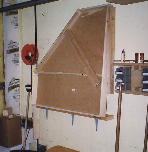 |
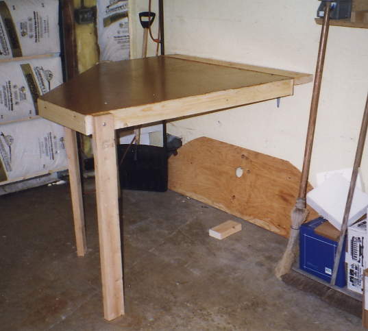
When visiting a Lancair builder to help him close out a wing, I noticed a really neat cut-off table for fiberglass bias-ply cutting. I made one for my shop (garage) but had to make it folding so I can use the space for other stuff when not cutting glass. It is 4’x4’, with one corner cut off so you can reach the glass for cutting. The roll of fiberglass goes against the wall, you unroll it, and lay a straight-edge across the fiberglass. Markings on the table let you line it up, and know whether you are cutting 2, 4, 6, 8, or 10” wide strips without having to measure. (Bill Schertz)
 It's a bit difficult to see but I mark a line on the glass and then use 5/8 in. masking tape to bind the glass along the line. I then cut the tape in half during the cutting operation. The tape is left on and cut off after the glass is wet. |
My cutting table is a pool table in my den.
It is really a nice way to layout the glass since it is easy to smooth the glass and maintain a good clean working environment. It is also very easy to work on cutting glass in any kind of weather. I have used the table for making my patterns and cutting the glass in bulk. I match the pattern to the glass, weigh it for determining the epoxy required and store them in large ziplock bags for future use. It does cause some problem with the bank shots however. |
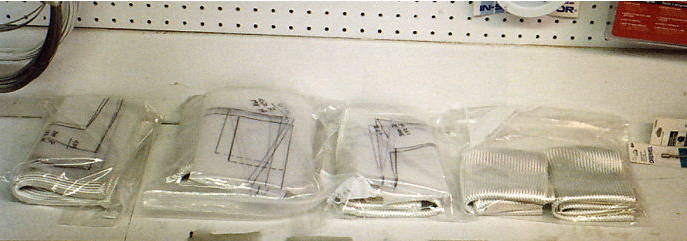 Here you see several packages containing both patterns and pre-cut glass needed for layups for installing the firewall and rear spar. I use quart size ZipLock plastic bags to hold my pre-cut glass and patterns to keep them clean and organized until I need them. |
|
If the plans call for a given number of BID layers in a strip of specified
width, it may be useful to prepare this strip on a plastic sheet. This will
allow more accurate trimming of the strip, and easier, low mess handling
of the material. The proper number of dry strips should be readied, a little
bit oversize in both directions. Lay out the proper number of layers of the
dry cloth on a sheet of thin plastic (garbage bag material will work, acetate
is excellent). Wet out these layers with the resin, using a brush trimmed
back for "stippling" the resin into the cloth. Wet thoroughly all layers,
and work any air bubbles out by "stippling" and/or squeegee in the direction
of the fibers (45 degrees). Thoroughly saturated cloth will take on a transparent
look. When the bubbles have been satisfactory dispatched, a second layer
of plastic material can be placed over wet resin. Additional air can be squeezed
out by pressing on, and working the top plastic surface with a squeegee.
The structural integrity of your completed aircraft and your personal safety, are dependent on bond joints that you make during the assembling of this kit. For this reason, these bonding areas must be absolutely clean and properly prepared as in the following paragraphs.
The "outer" surfaces of your premolded parts are very smooth where
they adhered to the mold during the pressure curing cycle. These surfaces
will have some residual material known as "parting agent (wax and/or PVA)"
that was used to keep the parts from sticking to the mold. Both this very
smooth surface, and the "parting agent" will be conducive in preventing a
good bond on any of these surfaces. These areas must be prepared by cleaning
and then roughing the surface (providing a "tooth" for the bonding agent),
and then cleaning away any "parting agent", dirt, dust, oil, or grease, and
even your finger prints that remain. The surface should be lightly,
but thoroughly sanded with an 80 grit abrasive paper until there is
no sign of the shiny smooth surface in any of the area where you will be
bonding. Do not sand through any of the cloth fibers in the laminate. This
surface should then be wiped clean with acetone or MEK to remove the dust
and any remaining contamination. Use one rag for wetting and scrubbing and
a clean rag for wiping. Don’t just move the wax around. Dry the surface
with the second rag before the part air dries. If it air dries, the contaminants
will be re deposited onto the surface. You must re clean the surface
to insure that no contaminants remain. Change to new rags
often.
Builders Note: The surface cleaning should be done just before
the application of the layups. Do not clean and then leave the surface
for a long period of time since airborne contaminates will accumulate on
the cleaned surface. (Bob Reed)
When using MEK or acetone, rubber gloves must be used to protect your skin
to prevent you from becoming ill and/or hypersensitive to the solvents. It
is suggested that you use rubber gloves as silicone (surgical) gloves will
desolve with MEK. Acetone will also soften surgical gloves. MEK is the preferred
material for removing the wax as it does not evaporate as quickly as acetone,
BUT the fumes are more harmful. A respirator, (not a dust mask) should
be worn or a large fan should be used to circulate the air when using either
of these chemicals.
Turn off that hot water heater and don’t let the furnace come on when
cleaning large areas with these chemicals.
WARNING acetone and similar solvents are toxic, and highly flammable. Perform these operations with good ventilation, well away from any sparks or flames, and avoid breathing the vapors. (even in a garage with the doors open, use a small fan to keep the air moving)
Many of the areas where you will be bonding will be surfaces where the "peel ply" was used in fabricating the part. The first step in these areas is a careful inspection to make sure that all fragments of the peel ply material have been totally removed in zones to be bonded. Again, it is important to remember that peel ply is designed NOT to stick, and will leave a completely unbonded area where-ever you have failed to remove it.
Once the peel ply has been totally removed, an adequate bond can be made,
but it is highly recommended that the same procedure of roughing the surface
with 80 grit paper, and subsequent cleaning with acetone be employed in these
areas also. Do not sand to heavily as the glass cloth is at the surface.
Builders Note: Peel Ply is also very useful
for application when doing wet layups. It performs several very helpful
functions and is quite easy to handle. It is applied as a top layer
on your layup and may be applied before or after the layup is applied. It
has a very tight weave and if oriented properly will keep your layup from
pulling out of shape during application. It will also help to soak
up some excess epoxy. After the layup is totally cured, the peel ply
must be removed and will leave a surface that can be used for additional
layups without sanding. A final benefit to peel ply is that when applied
with a wide overlay beyond the surface of the bid, it will serve to smooth
the layup into the surrounding surface.
(Make sure and use a peel ply as supplied by an aircraft supply company since
it will not have any chemical coatings on the material. The peel ply
tapes which come in 2,4, and 6 inch widths are not recommended since
they tend to be too heavy for many peel ply applications. The lighter
peel ply will conform to odd shapes much easier. Tapes are only usable
on smooth flat surfaces. ) (Bob Reed)
MICRO and FLOX are terms used to describe two common types of filler material used with epoxy resin systems. Both of these materials are provided with the kit, and are identified by name.
MICRO is a shortened description for micro-balloons, which are tiny hollow spheres of either glass or phenolic plastic. These spheres are so tiny that it is a powder almost as fine as flour. These can be mixed with epoxy resin to make it thicker and easier to use as a filler. For general purpose, enough MICRO is added to the resin to make it a thick paste about like a putty. This would be thick enough to squeegee a thin layer on a vertical surface and not have it "run" or sag. For bonding or laminating to foam surfaces (covered in more detail later), MICRO is mixed as a slurry, which is about like a thick creamy paint. In some instructions you will see reference to "dry MICRO", this is a thicker mix which will appear almost dry (about like a snowball), but will have enough resin content to allow it to adhere to clean surfaces. MICRO will result in a structure which is significantly lighter than solid resin and will be less brittle, though not very strong. MICRO mixes are frequently used in adhesive applications, where the thickened "paste" can fill voids, and not run out of the joint as straight resin would be apt to do.
FLOX is the term applied to finely chopped fibers (usually cotton) which also is frequently mixed into the epoxy resin to make it thicker and more "pasty", for use as a filler and/or adhesive. With this filler, the usual mix will be thickened to almost a putty consistency. (Generally FLOX is used a bit wetter than MICRO). The fibers add structural integrity, and avoid the brittle nature of unfilled solid sections of cured resin. The FLOX mix is heavier than MICRO mix, and is not as easy to use as a filler, and is significantly stronger. Chopped glass fibers have been used in a similar fashion on occasion, but they are heavier and more difficult to work with.
In this kit, frequent use is made of a mixture of roughly half and half of
these two filler materials with the resin system, and this will be called
a MICRO/FLOX mix. This usage provides a compromise between the characteristics
of the two filler materials, and combines some strength improvement of the
FLOX with the lighter weight of the MICRO. A typical use is in what is called
a "FLOX/MICRO joint" where a layer of glass crosses the edge of another glass
layer, and structural integrity is desired in the joint between the two.
The sketch (Figure 1-2) shows how the foam is "chamfered" out to make a
triangular recess which is then filled with the FLOX/MICRO paste.
For a higher level of structural strength the same technique is used but
with a straight FLOX mix.
 |
The resulting fillet of filled epoxy resin provides the required structural connection between the intersecting glass layers, and avoids trapping air bubbles in the structure. (Air bubbles weaken a joint or lay-up significantly and should be diligently avoided when filing these joints). Frequently a size will be specified for the MICRO/FLOX joint, and that dimension refers to the legs of the triangular cutout in the same fashion as for a chamfer specification on an engineering drawing.
When a bulkhead is bonded to another structural member a sharp 90 degree angle will usually be formed. The glass cloth cannot form around a direct 90 angle so the corner must be filled with a micro flox mixture creating a smooth rounded surface for the glass to form to and adhere to. As shown in figure1-3, a small fillet is added (approximately ¼" radius) before the glass is applied. It is best to apply the glass to the fillet material before the fillet is cured. If the fillet cures, roughen the fillet before applying any glass cloth.
 |
Builders Note: There will be many situations requiring the use of fillets or beads of Flox, Micro, or Micro/Flox. There are several ways to lay down these fillets. The easiest, least expensive and quickest way I have found is to use Cake Icing Tubes, which are clear plastic cones that can be filled with the Micro/Flox mixture. Once filled with the mix, cut the tip off the cone and twist the cone from the top to squeeze out the mixture along the desired line. Use a rounded wooden hobby stick to smooth out the fillet and remove any excess. (Bob Reed)
BONDING AND
LAMINATING TO FOAM
The raw surface of most foam core materials is rough and somewhat porous
in both appearance and fact. Using straight epoxy resin for bonding to this
surface will produce a heavy joint with rather spotty adhesion performance.
Invariably some of the resin in the bond area will run or "wick" away leaving
bubbles and unbonded areas. Also the large amount of resin used in an attempt
to fill the surface of the foam will add a lot of unnecessary weight in the
structure. The solution to this problem is to "prime" the foam surface with
a MICRO slurry before laminating the cloth to this surface. A "slurry" used,
as discussed above. The thickening effect of the MICRO will make the mixture
stay in place better than straight resin and the MICRO balloons will
significantly reduce the weight of this mixture. The weakening effect of
the MICRO fill is not an issue with this application since it is still many
times stronger than the foam substrate to which it is bonding. The slurry
is applied to the surface with a squeegee, basically filling the surface
pours. Some builders allow this filler to cure, and then sand it smooth,
but the most common and quite effective technique, is to lay the glass cloth
on the wet uncured surface, and add straight resin the surface of the cloth,
brushing and stippling the resin into the weave. As in all laminations of
glass cloth, squeegee away the extra surface resin to make a surface which
has no bubbles, but the weave is plainly visible.
Surplus resin only adds weight not
strength.
A technique frequently used when laminating parts with the BID cloth which will give a nice edge without sanding or filing is called "green trimming". When laying the wet cloth on shaped parts, the only way of assuring complete coverage is for the edges of the wet cloth to overhang the edge of the part. It is good practice to use generous amounts of this overhand to assure that the cloth is properly wet out up to the edge of the part below. During the cure process, epoxy resin goes through a stage where it is described as "green", where it will have a rubbery character with about the pliability of beeswax. At this point it is fairly easy to trim the overhanging cloth with a sharp clean utility knife or razor blade. Determining the time to do this is a trial and error proposition, and will vary primarily with ambient temperature. When working in cool evenings you may end up losing some sleep to meet this proper trimming time. Test frequently with the point of your knife to see when this rubbery stage is reached, if you wait too long your alternative will be to sand, saw or grind back this edge. As mentioned above, the time to reach this point will vary from not much more than an hour in hot weather to several hours in cooler temperatures. When cutting the BID, cut down through the BID towards the part underneath so that your knife acts as a shear. Do not cut upwards as this may pull the BID away from the part you are trying to stick the BID to.
Always be sure that if the knife slips neither you nor the part will be injured. Do not attempt to use "Green trimming" to clean up the edges of glass tape laid as seam strengthening on the premolded parts, as the point of the knife will damage the fibers in the structural part beneath the cut at the "trim line" and lead to potential failure.
FOR THIS REASON NEVER CUT AGAINST STRUCTURAL COMPOSITE MATERIAL