N247BR
Vertical Stabilizer
| The Vertical
Stabilizer is comprised of two premolded components which are joined
together forming the upper portion of the rear fuselage, the dorsal
fin, and the vertical stabilizer. |
|
 |
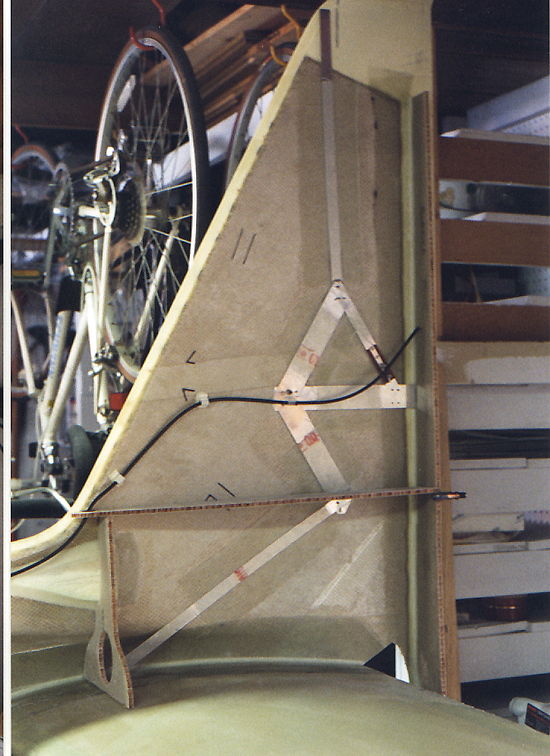
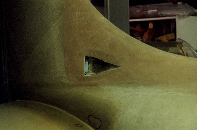
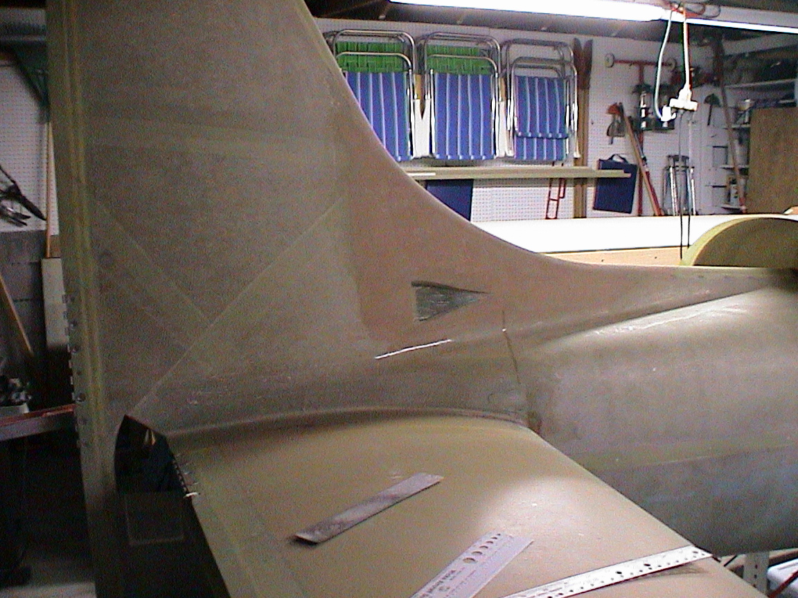
Trial fit of the vertical stabilizer prior to installation of the horizontal stabilizer. The cutout for the horizontal stabilizer has been made and the supports for the horizontal stabilizer are also shown temporarily in place. I recommend holding onto those cutout portions and using them for filler once the horizontal stabilizer is installed. |
 |
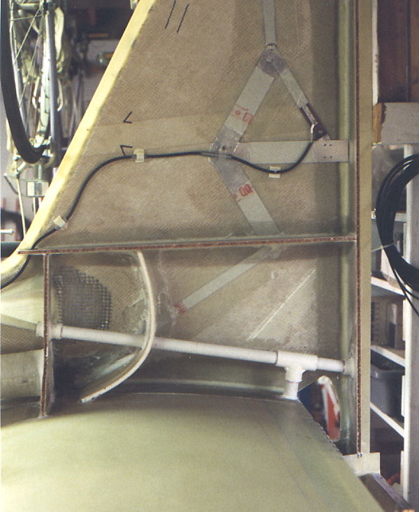
After the Horizontal Stabilizer is mounted ,the right side of the Vertical Stabilizer is mounted and bonded to the Vertical Spar and the Horizontal Stabilizer. Prior to installation of the rib the Communication Antenna should be installed. The above photo shows the full spread of the communications antenna. The one used is from Bob Archer and was glassed into place with single ply bids. As can be seen from the above photo, it just barely fits. |
|
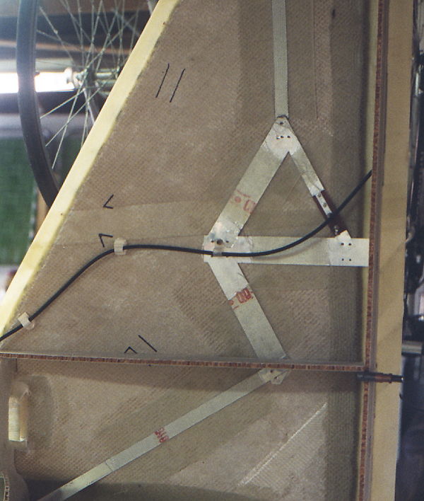 |
I tried several different mounting arrangements but all had some conflict. The black marks on the photo above show the only alternate mounting which would work as well. I picked the above arrangement since I was concerned that the electrical bonding cable which will run up the rear stabilizer spar would interfere with the signal.
|
|
|
Now if this looks a bit strange, did I mention that my wife had ask that I install in-plane plumbing? This shot shows several additions which I have incorporated. First the plumbing, it's conduit for the electrical wiring to the rear strobe and trim servos. The idea is to provide an easy, non-restricted path for running the electrical wiring. Like the conduit in the wings, this provides a clear path for the wiring and one which can be serviced in the future. The curved panel is an air baffle to route the incoming air from the NACA scoop and through the tube just above the horizontal stabilizer. The NACA air scoop can be seen just in front of the bulkhead. The outlet from the scoop is covered by a wire screen to keep unwanted critters from getting in. |
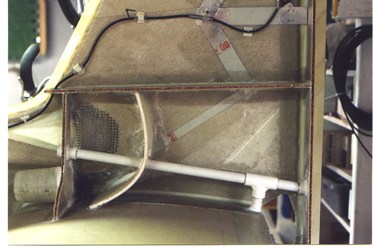 |
What can't been seen here is the drain tube which is in the lower corner against the fuselage wall. This will allow any moisture accumulation to be removed. Prior to closure, the air box was closed with a prepreg panel and glassed into place. I closed it out separately because I felt it would be impossible to get a good seal on the air box with the other side of the vertical stabilizer. This way I could seal the box without having to make the airbox airtight within the stabilizer. Prior to closure I also potted an epoxy-flox mixture over the antenna connections. |
 |
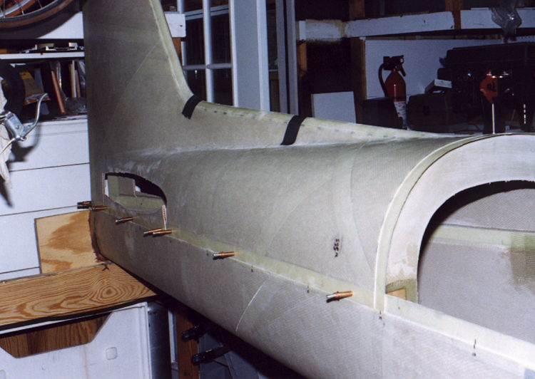
I used a number of
different clamping methods to close out the vertical stabilizer and the
fuselage section. The strap clamps were great for putting
pressure on the area around the bulkhead and for the lower portion of
the stabilizer. The vertical portion of the stabilizer I used
some wood clamps and a 1 x 2 hardwood strip. The wood clamps
worked great because they can be closed in on the same angle as the
stabilizer. The hardwood strip helps keep the sides of the
stabilizer nice and straight with even pressure along the stabilizer
spar. I used matching 1x2 wood strips on the inside and outside
of the fuselage held tightly together with drywall screws to clamp the
fuselage together. 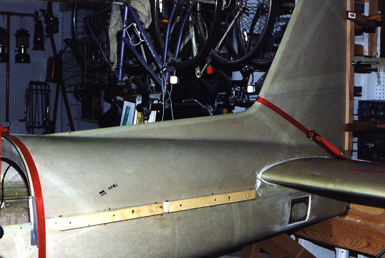 |
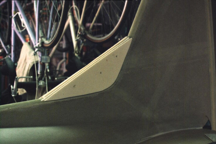
| The new factory demonstrator shows a modified dorsal fin which looks really nice. Prior to seeing it I had already decided to do a similar modification on mine. Seems that I was not alone since the photos of the KIS Cruiser in New Zeland also show a similar modification. These photos detail the steps I used to form a modified upsweep in the dorsal fin. | |
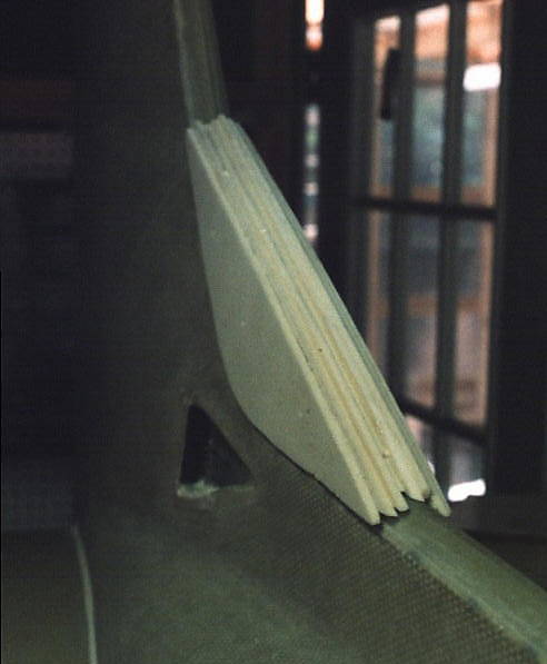 |
I don't know if this is what the 1/4 inch foam was
intended for but it was an effective means of forming the necessary
filler for the new dorsal fin. I bonded several layers of foam
together using a micro-epoxy mix and fit this on the existing
structure. This was then bonded into place and allowed to cure.
I followed up using a light weight micro filler to fill
in the gaps. A rasp and file was used to shape the structure.
Additional filler was used as necessary to get to the final
shape.
|
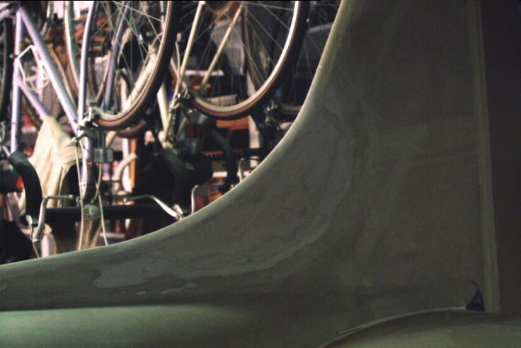
| Once the shape was close to the final desired shape it was covered with two layers of prepreg. A final sanding and some thin filler and the new dorsal fin is complete. | |
 |
 |
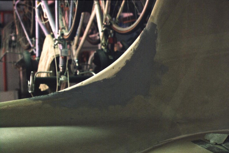
| The final dorsal
fin modification was cleaned up, sanded and a light weight glass
applied to make everything flow smoothly into the other parts.
The black circles on the first photo were bubbles identified in the
glass layup that had to be rrepaired. |
|
 |
 |
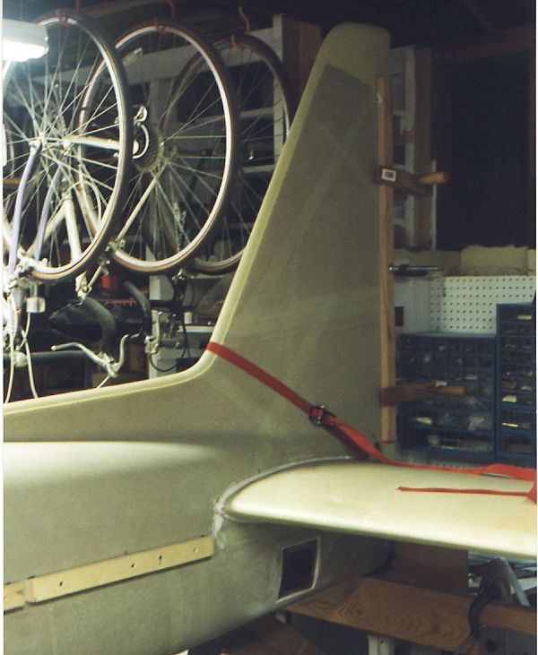
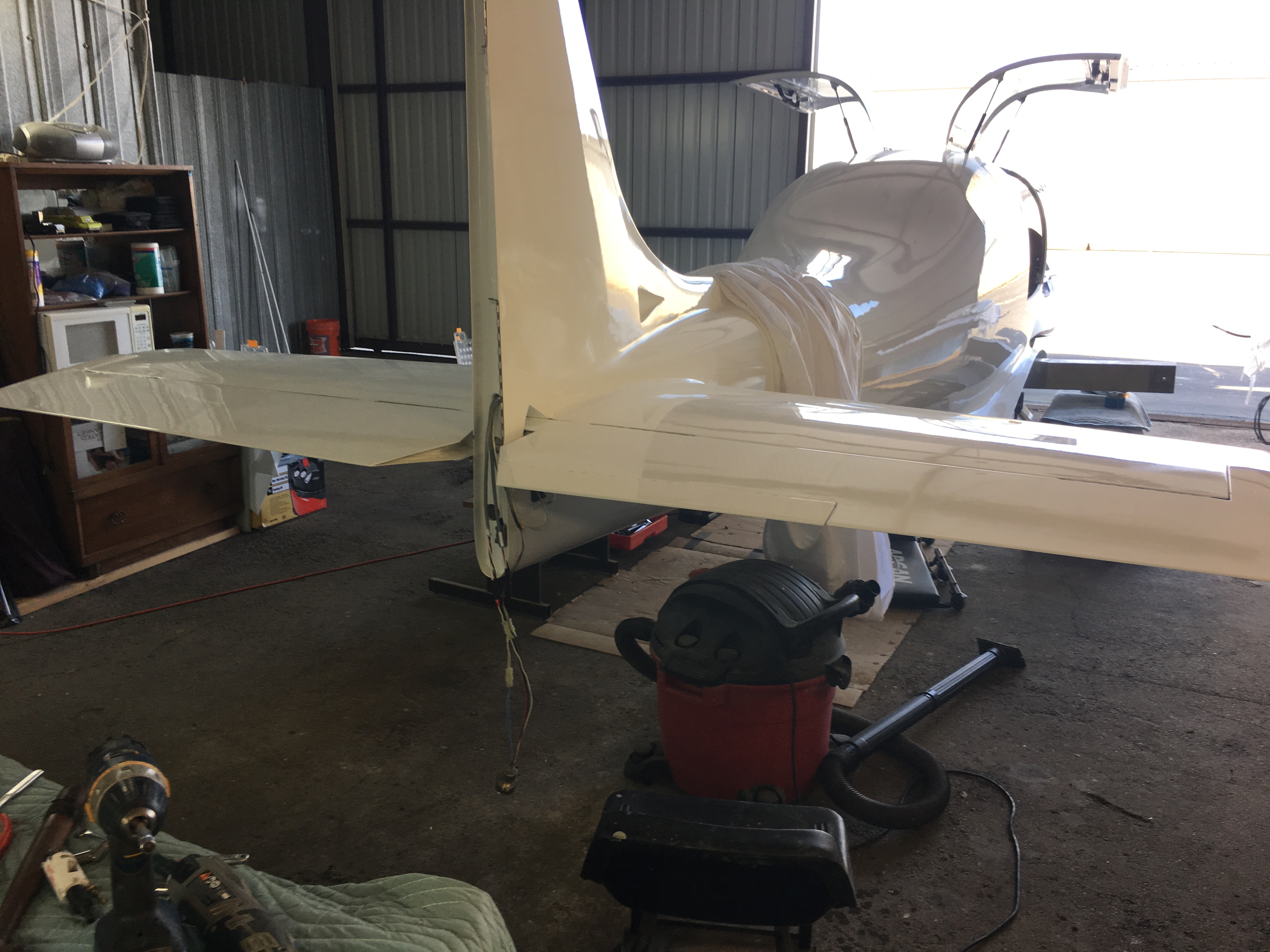
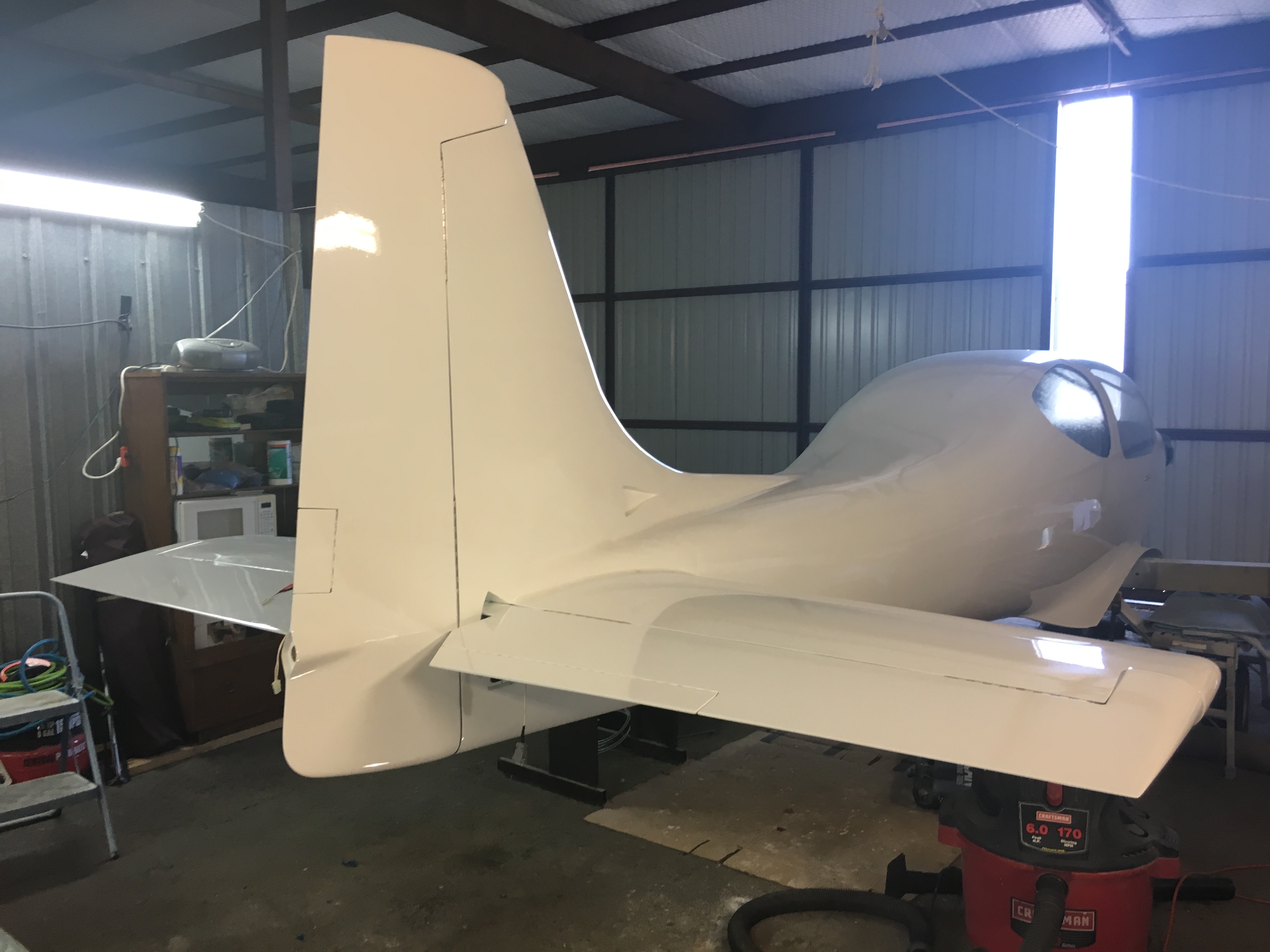
| Didn't take a lot of photos of the vertical
stabilizer after the initial finish on the glass work but the bottom
two photos show the final product with everything painted and installed. |
|
 |
 |