
N247BR
Rudder
|
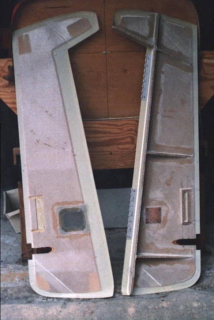
Here are a few preliminary photos of the rudder construction. There have been a number of discussions regarding problems with rudder fit. Several have reported "Fat" rudders when the rudder was too thick to properly fit the rear spar of the vertical stabilizer. I lucked out on that aspect and did not experience that problem. I did not entirely escape all problems with the rudder though. Two different problems have cropped up during my rudder installation. The first problem resulted from the way the tail of the fuselage was positioned in the jig for working on the fuselage. It put some pressure on the structure which resulted in the lower part of the rear being a bit wider than it should be. This resulted in a larger gap at the lowest part of the rudder. I also had a problem with my vertical positioning of the rudder. I thought I had it positioned correctly and had all the holes drilled but after close out found it was about 1/4 inch too high. I haven't worked out all the fixes yet but shouldn't have any real problem with this. I will wait until I have the fuselage on the gear before proceeding further. |
||
 |
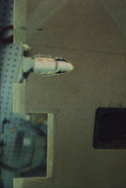
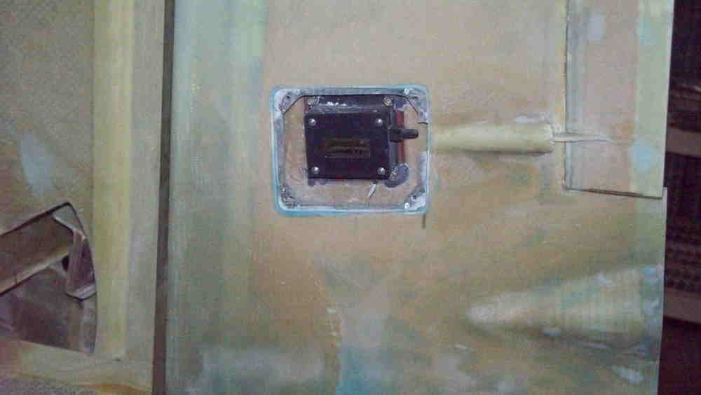
Inside view of rudder just before closeout. Inspection panel and trim servo mouting can be seen. Trim tab is outlined and will be cutout once full rudder is closed. The cutout from the trailing edge is the opening for tail light. Exterior view of rudder prior to final close out. Outlines can be seen for inspection panel and trim servo as well as trim tab. |
 |
 |
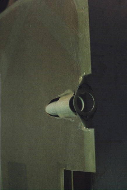
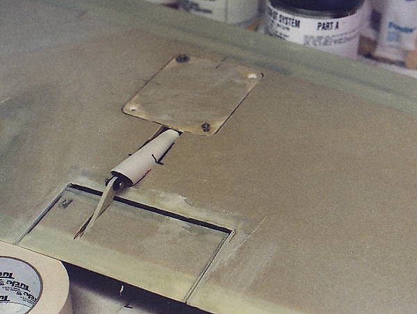
I found that the tail light fit just perfectly into a PVC pipe joint expansion end. This view shows the pvc pipe being bonded into place. I made a combination nut plate and mounting bracket from a six ply layup. This view shows the nut plate bonded into place using 5 minute epoxy and flox. This forms a very good bond. |
 |
 |
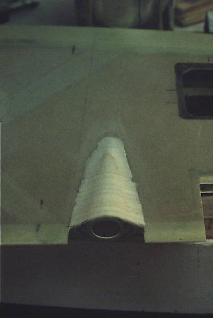
This looks rather crude but I used layers of the 1/4 inch foam included in the kit. The layers of foam are bonded with a thin micro/epoxy mix. The idea here is to just fill in the rough shape. Remember, this is nothing more than a framework for the glass and has no structural use. A little filing and sanding and you have the exact shape ready for covering with a couple of plys of glass. The whole thing only took a couple of hours to work out. |
 |
 |
As you can see, it works out and looks a lot better once the glass is on and you smooth out the edges. Here you can see the tail light in the proper position. You can also see the preliminary work on the trim tab and servo. This shows the other side of the |
 |
 |
This shows the acces cover and servo control guide being roughed out. The trim tab is positioned and being trimed out. |
 |
 |
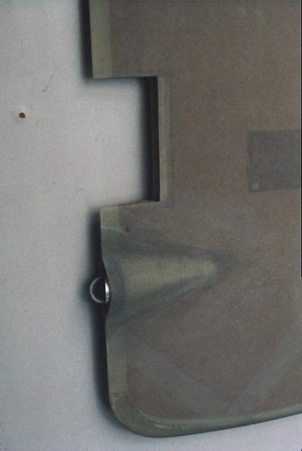
The rudder hinge used nut plates
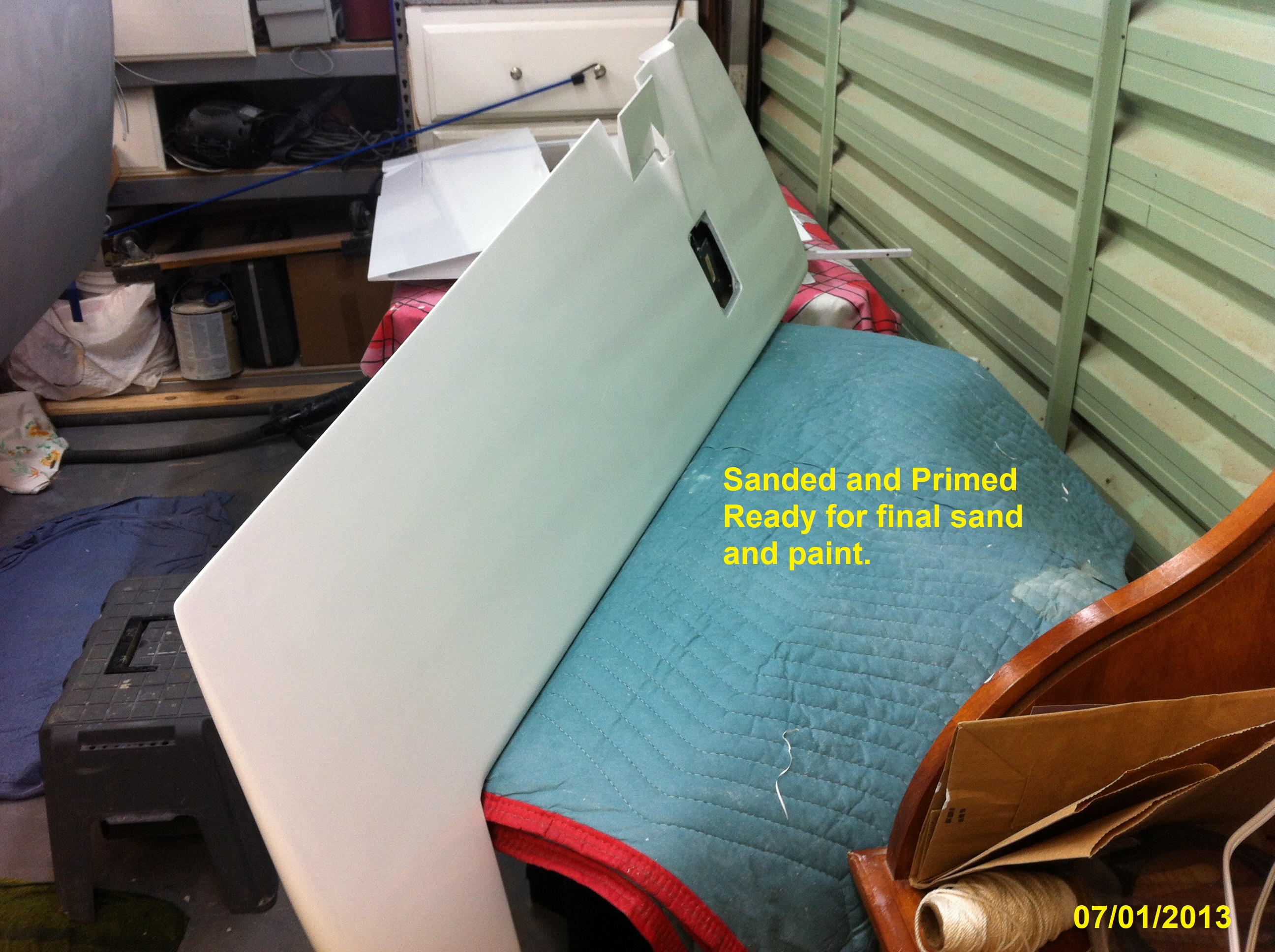
and a removable hinge. Simple enough until you try to do the final install through a half inch opening. Started finish work at home but the paint did not adhere properly and I had to sand it down and repaint later. |
 |
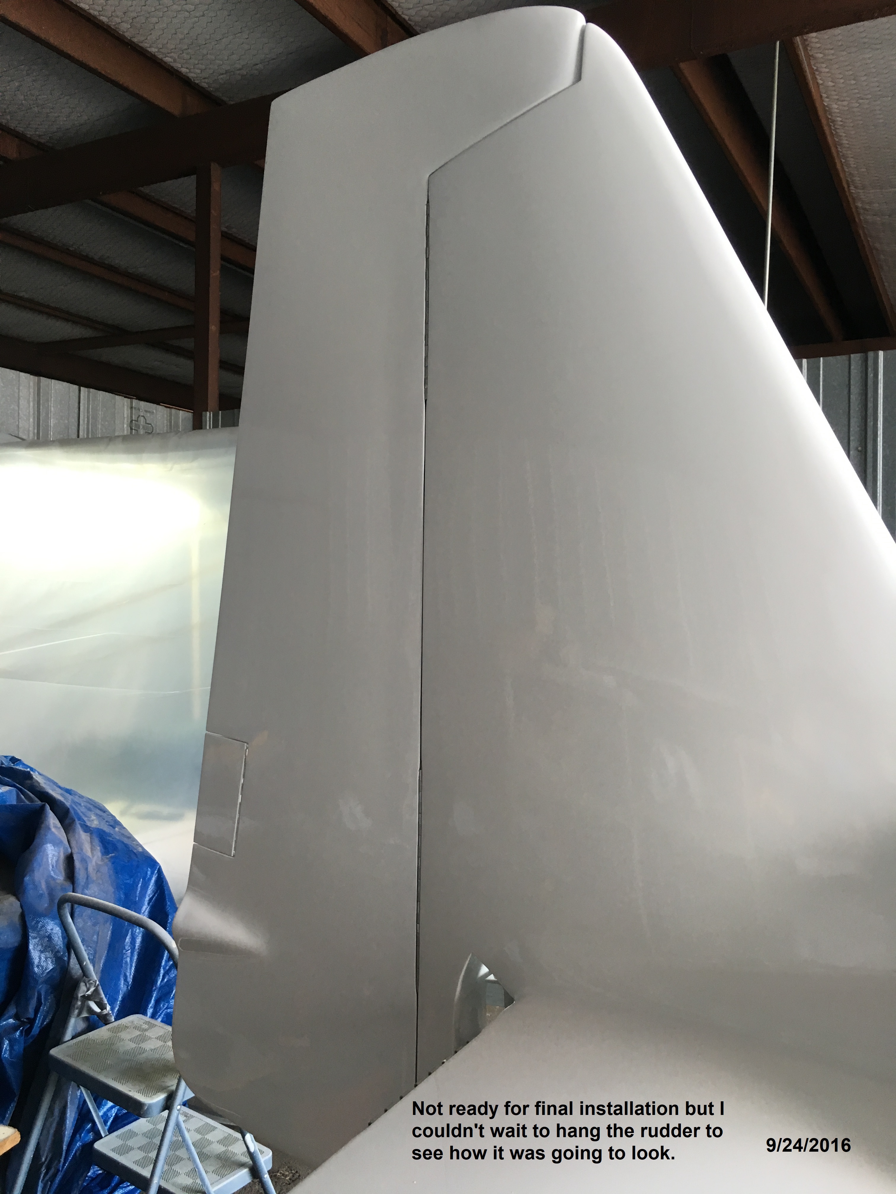 |
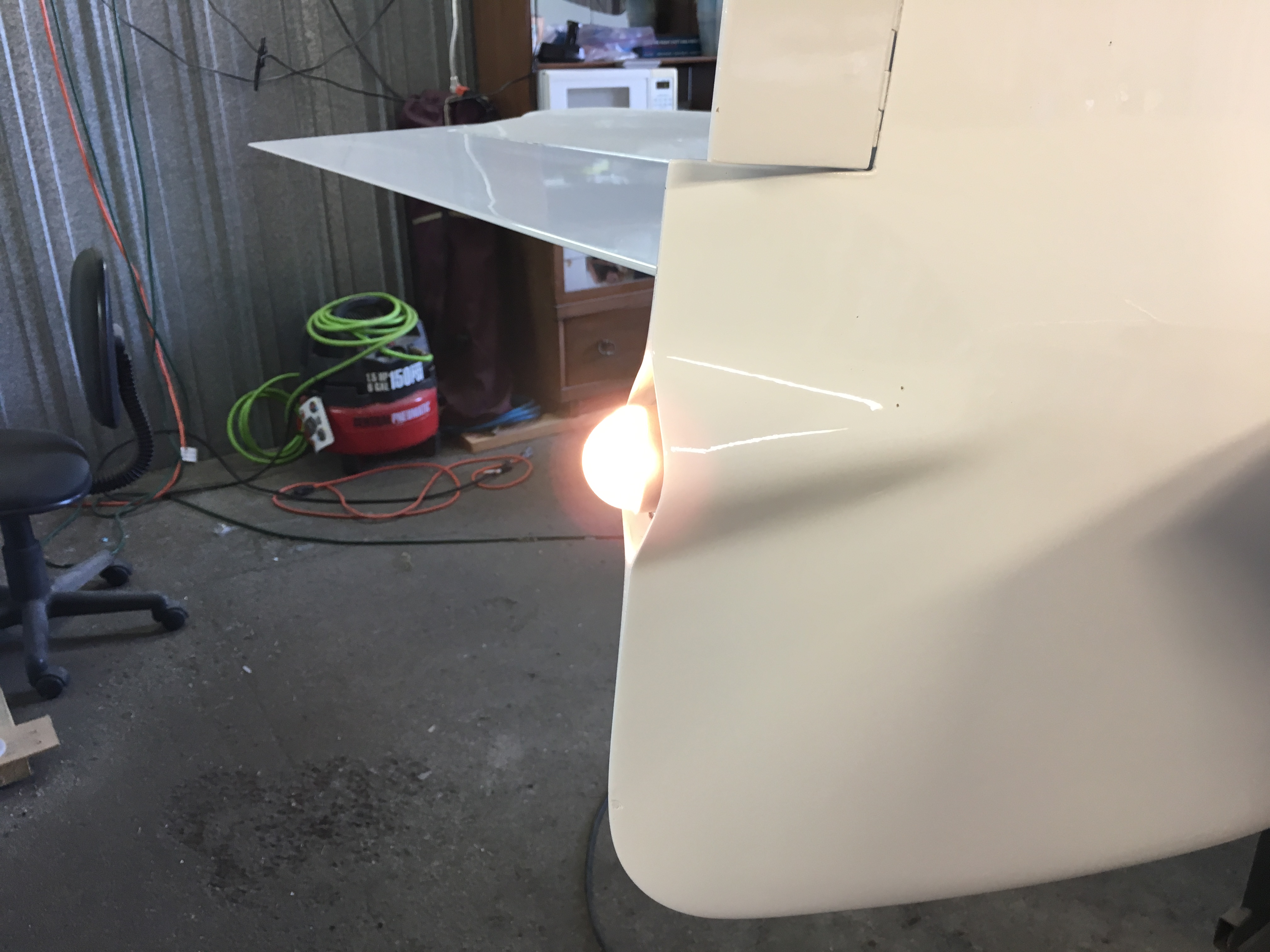
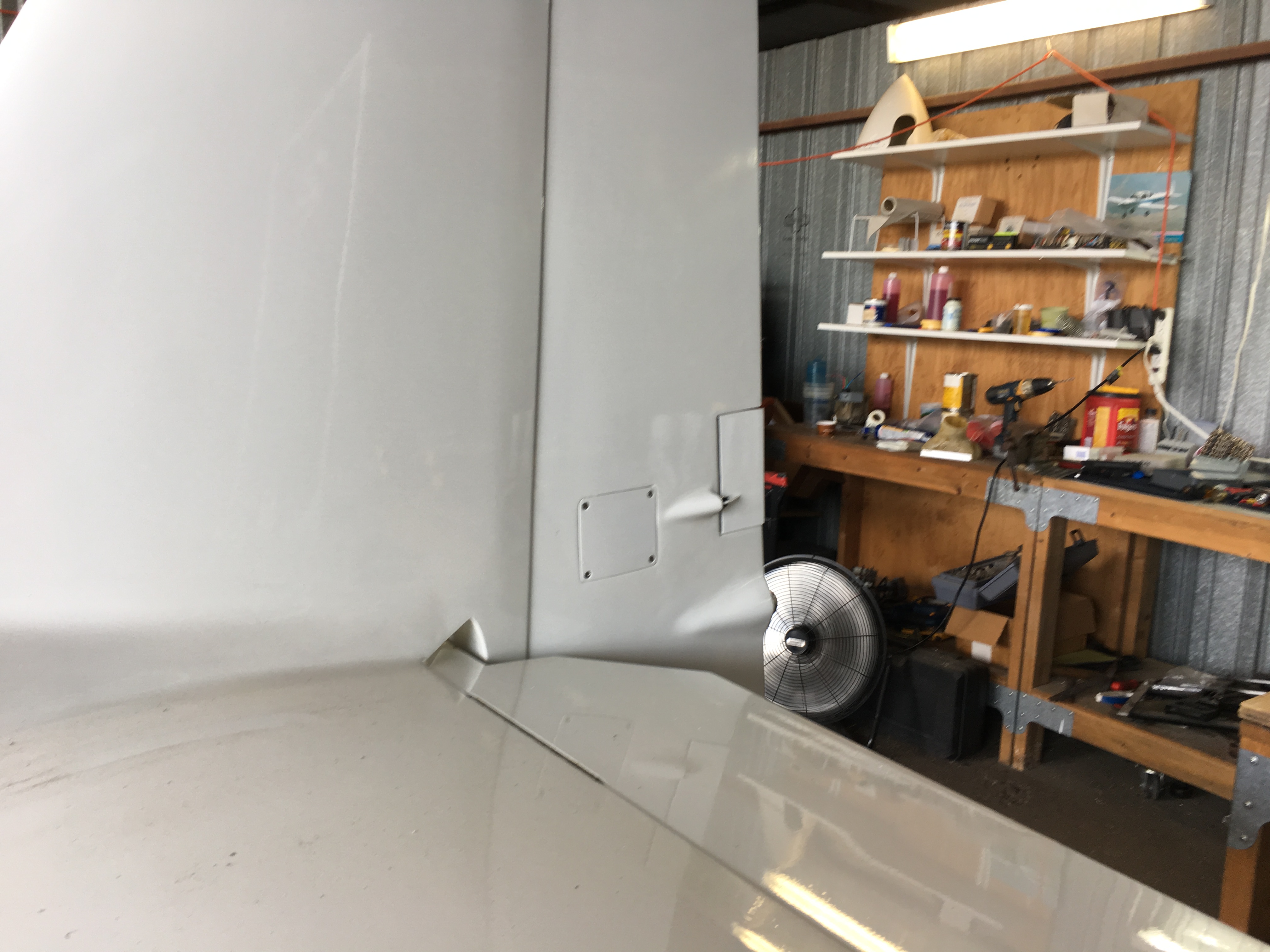
The final product after painting
and installation looks good if I say so. The hinge screws are hidden and glassed over before painting. The hinge uses a removable hinge pin and is safety wired into place. Not the easiest process to perform through a 1/2 inch wide space by yourself. |
 The tail light as been installed and the trim tab has been completed and tested. |
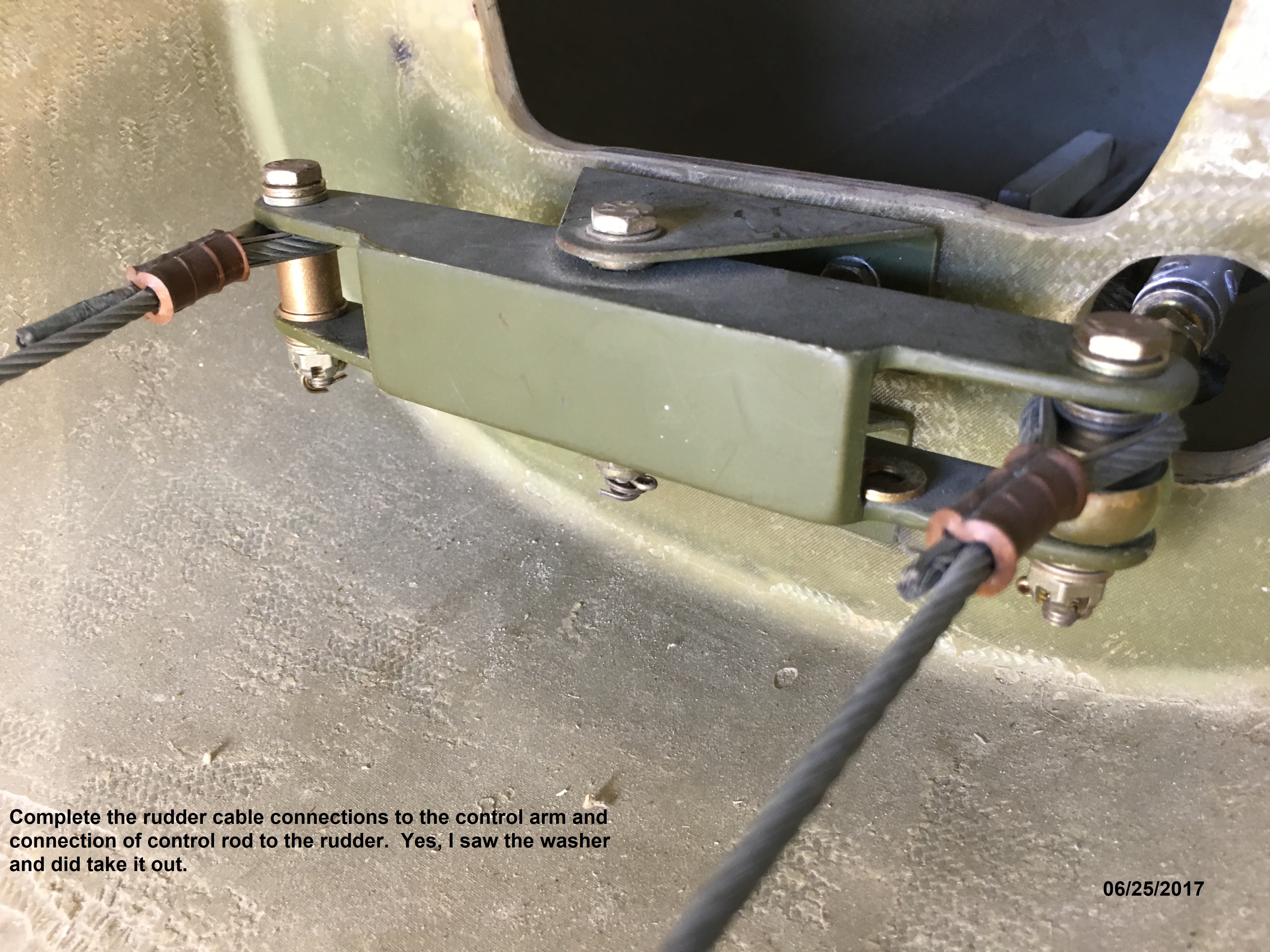 |
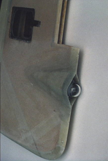
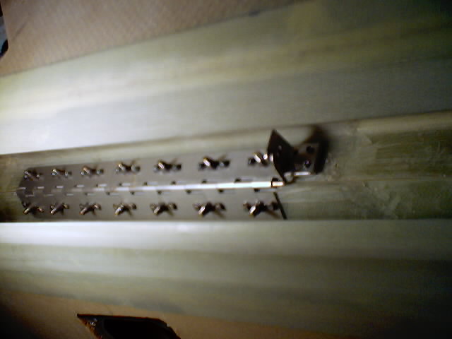
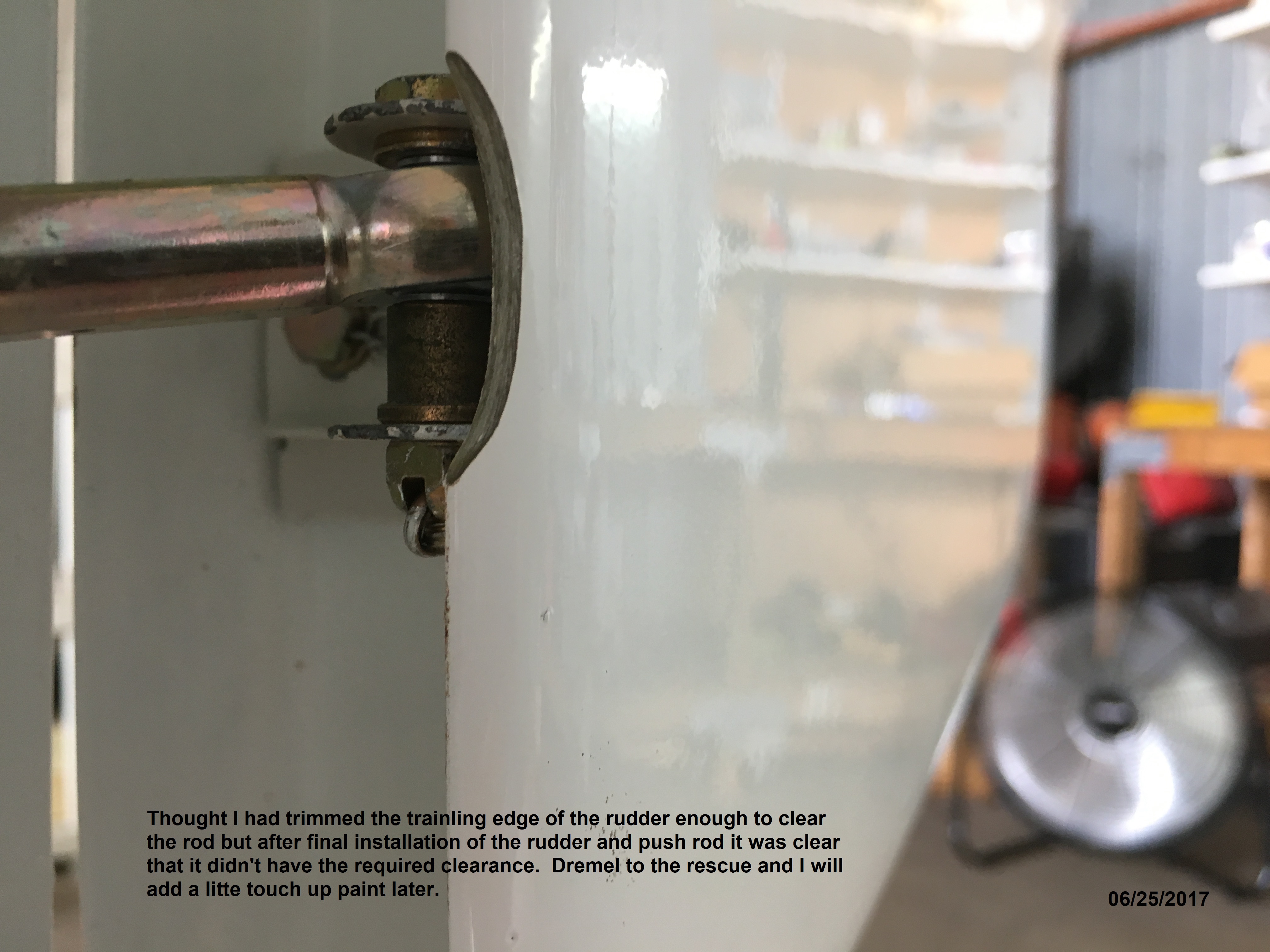
The rudder cables attach to a
pivot bracket that pushes a control rod to the rudder. The control rod attaches to a bracket in the rudder. Making the connection was so much fun through a very cramped opening. I had to trim the lip to allow the full rudder travel without binding. |
 |
 |
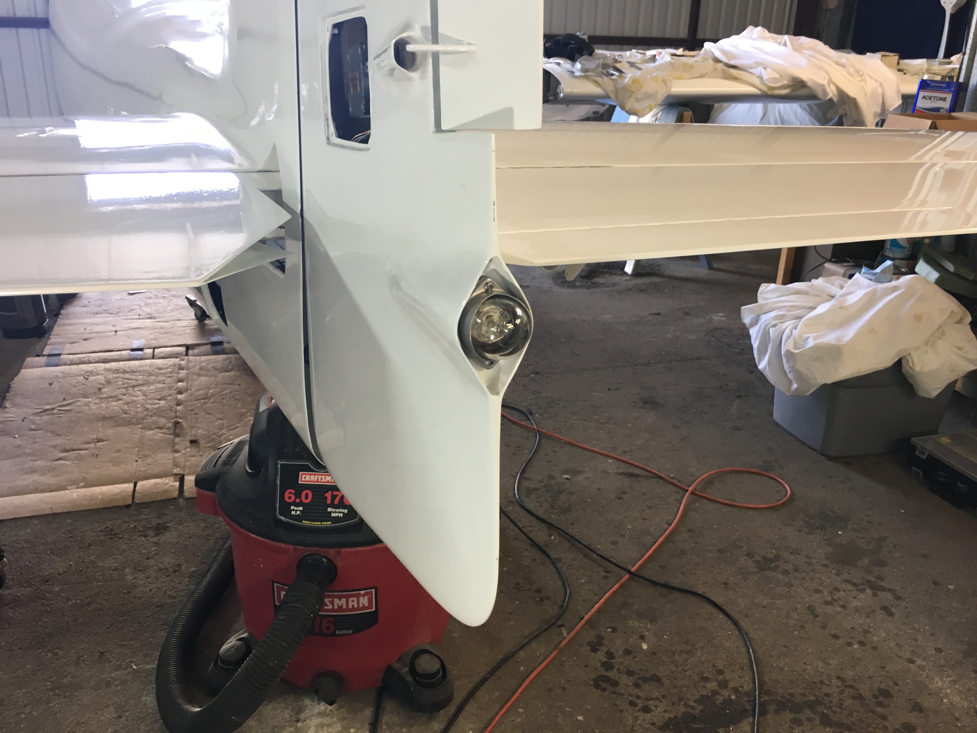
Last but NOT least the tail
light actually works. Wonder of wonders. The closed up rudder with everything finished is done. |
 |