|
After looking for an off the shelf exhaust system that
would fit
my requirements and not finding a good match I decided to give Aircraft
Exhaust Inc. a call about their design your own Custom Exhaust
System.
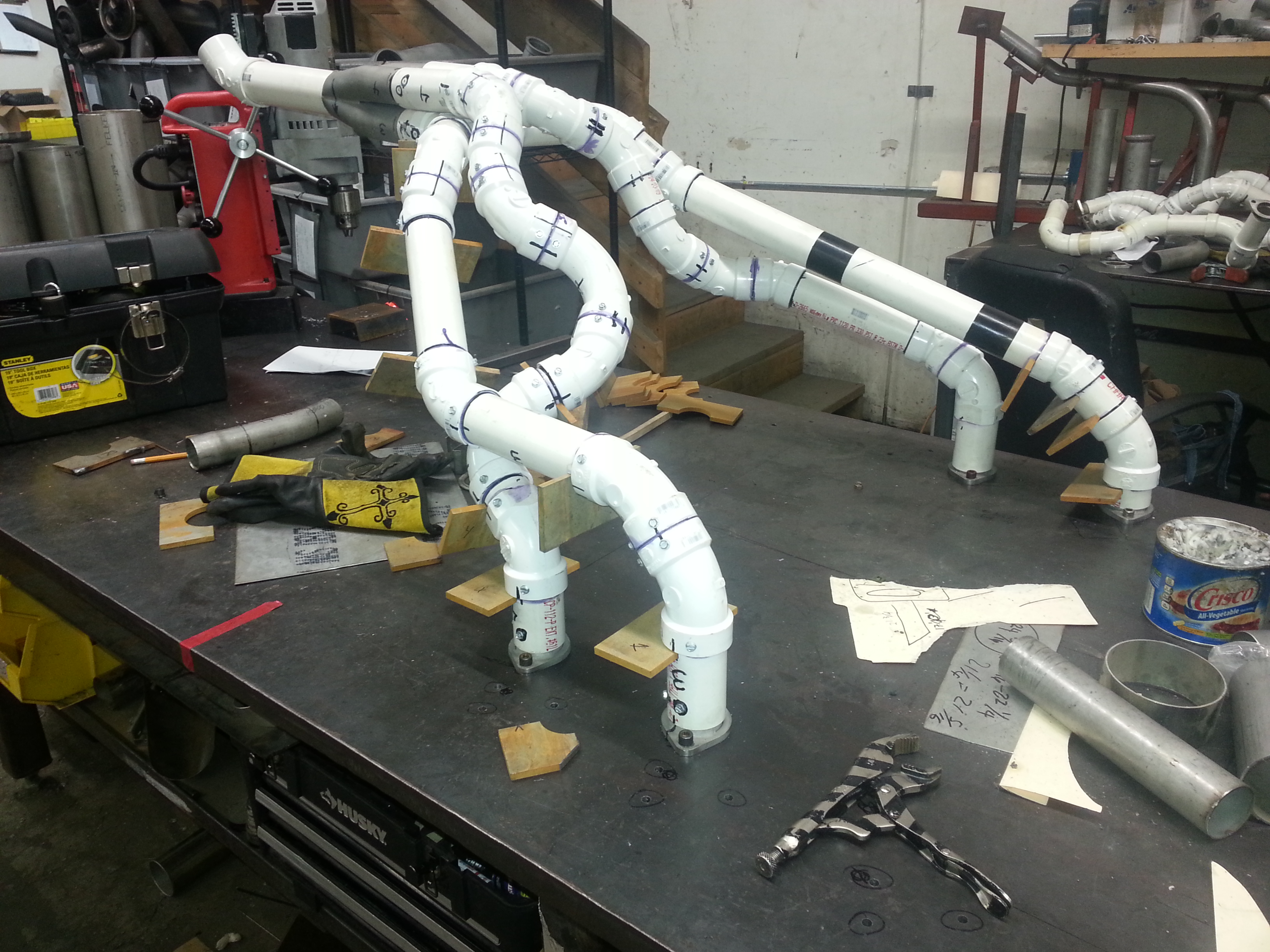
The process starts with obtaining a collector
based on your requirements and the
exhaust port connectors from the custom exhaust manufacturer. You
supply the
necessary PVC pipe and joints to custom design a system to your exact
requirements. The following show the completed mockup to be sent
for
fabrication.
While I was working on the fabrication of the
system a couple of other
pilots who have planes on the field where I have my hangar stopped by
to
see what I was doing. One of them was familiar with the process
and
started discussing it with me. The other had absolutely no idea
of
what I was doing...only that I was building my exhaust out of plastic.
Finally after about 10-15 minutes he couldn't take it any longer
and
asked "Aren't you afraid that your exhaust will melt?". I thought
his
friend was going to laugh himself sick. We finally explained that
this
was just a mockup and it would be used to build a stainless steel
version.
|
|
 |
 |
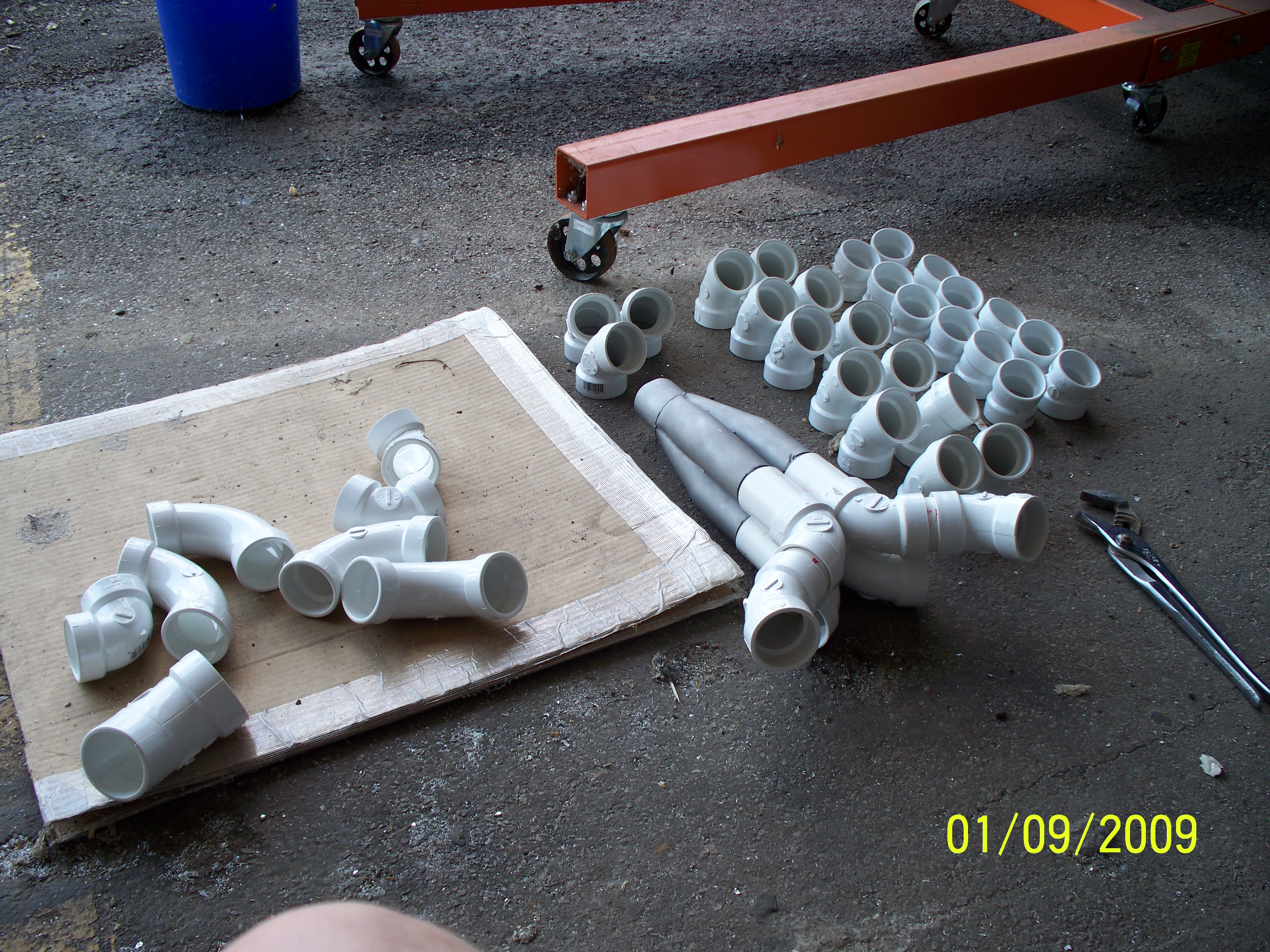
| A trip to Home Depot resulted in a
good supply of 90, 60, 45, and 22.5 Degree PVC connectors and several 2
foot lengths of PVC pipe. Get more than you will need, you can
always take some back. |
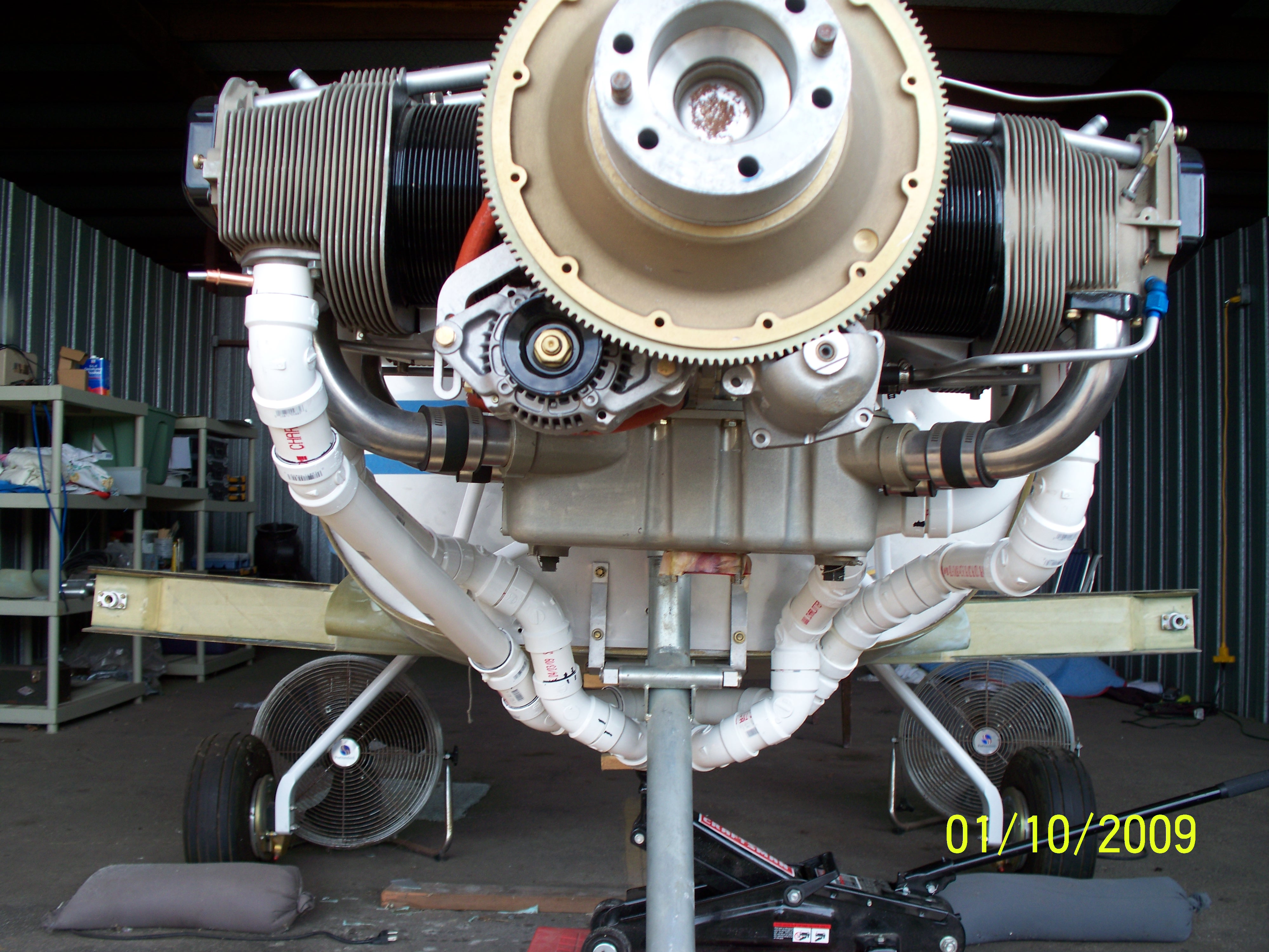
Start by mounting the collector
where you want it to be positioned when complete. It must be
placed and held firmly in position while working on the assembly.
The process will take lots of fitting and refitting. |
 |
|
|
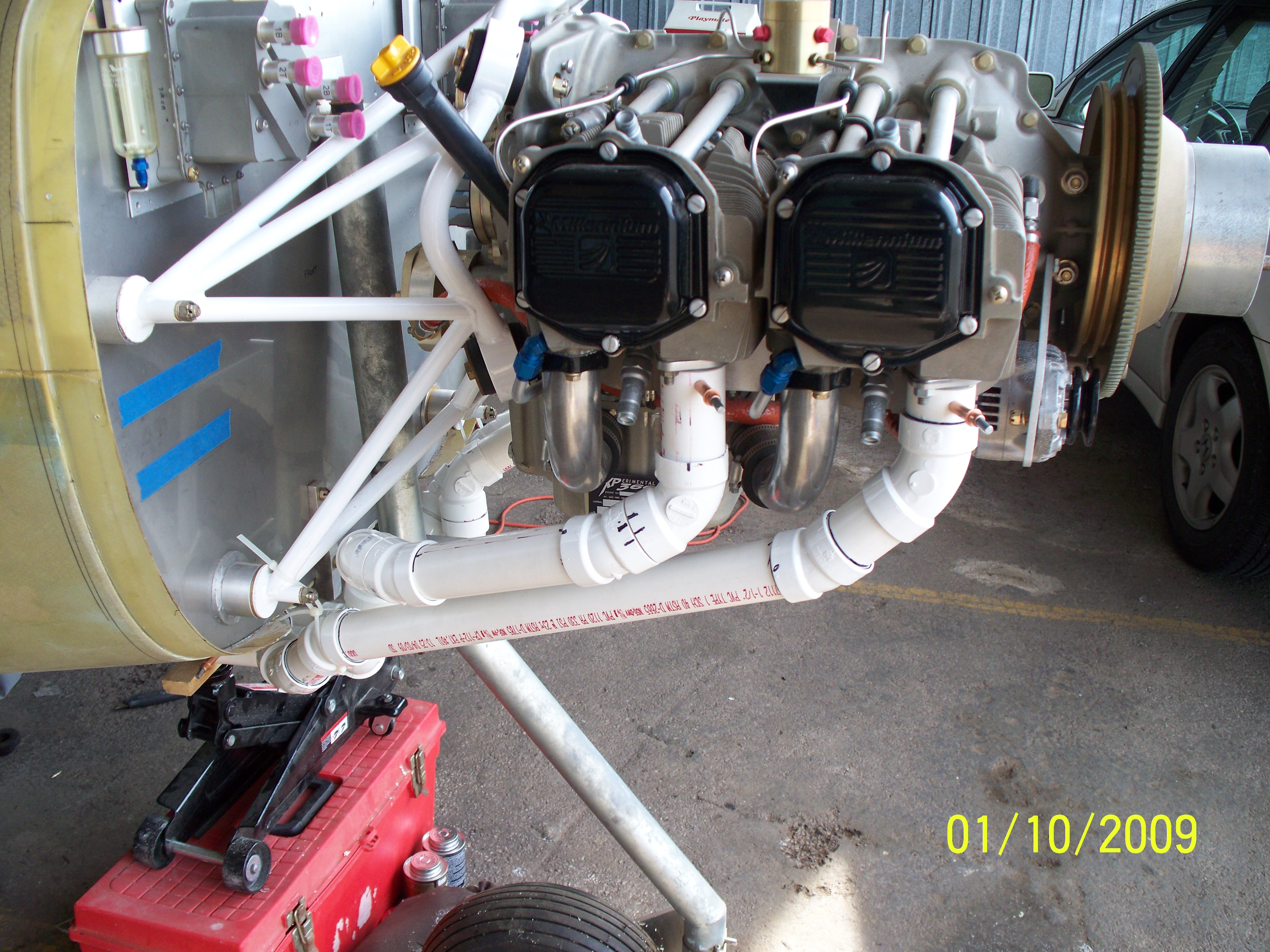 |
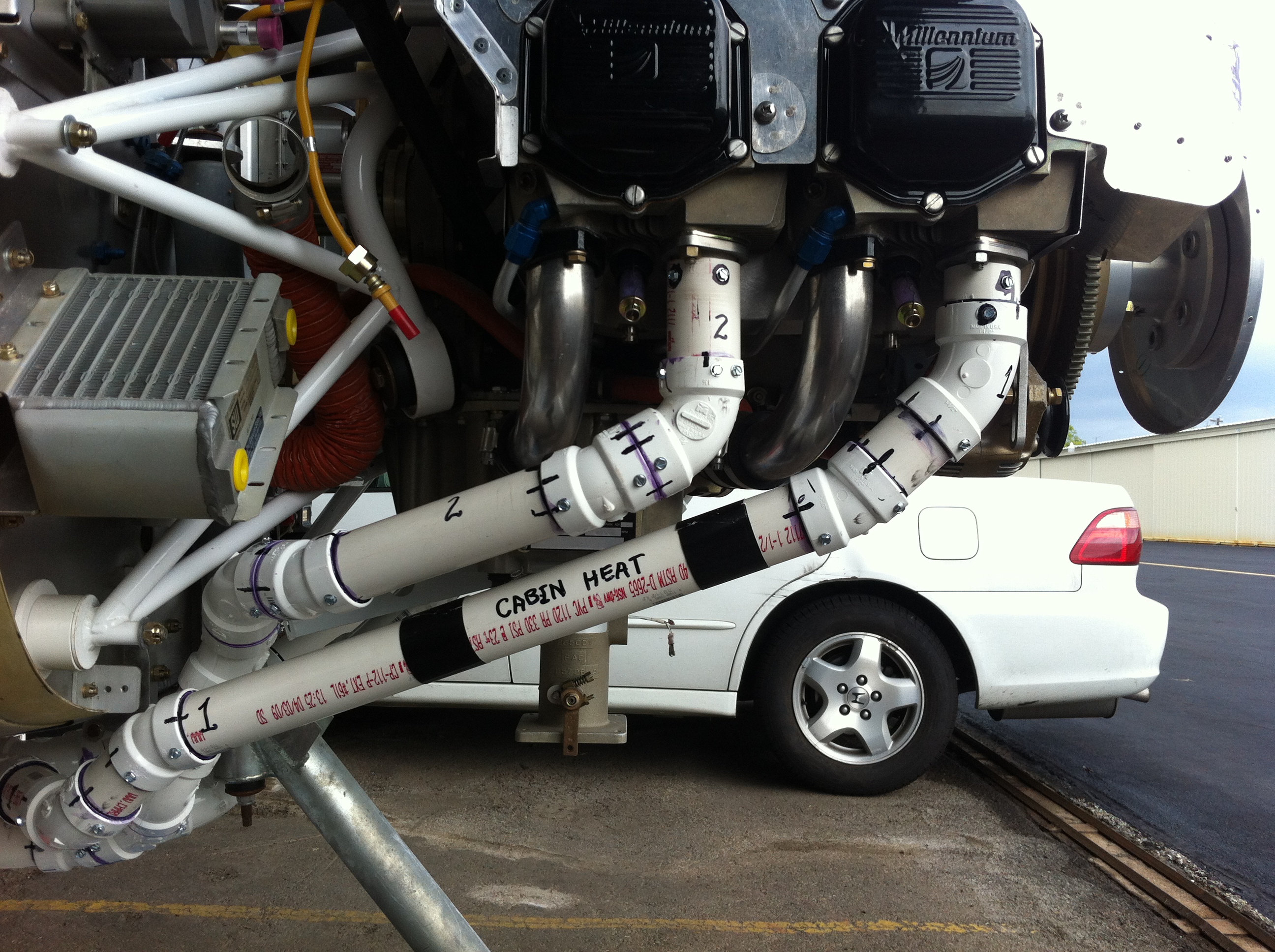
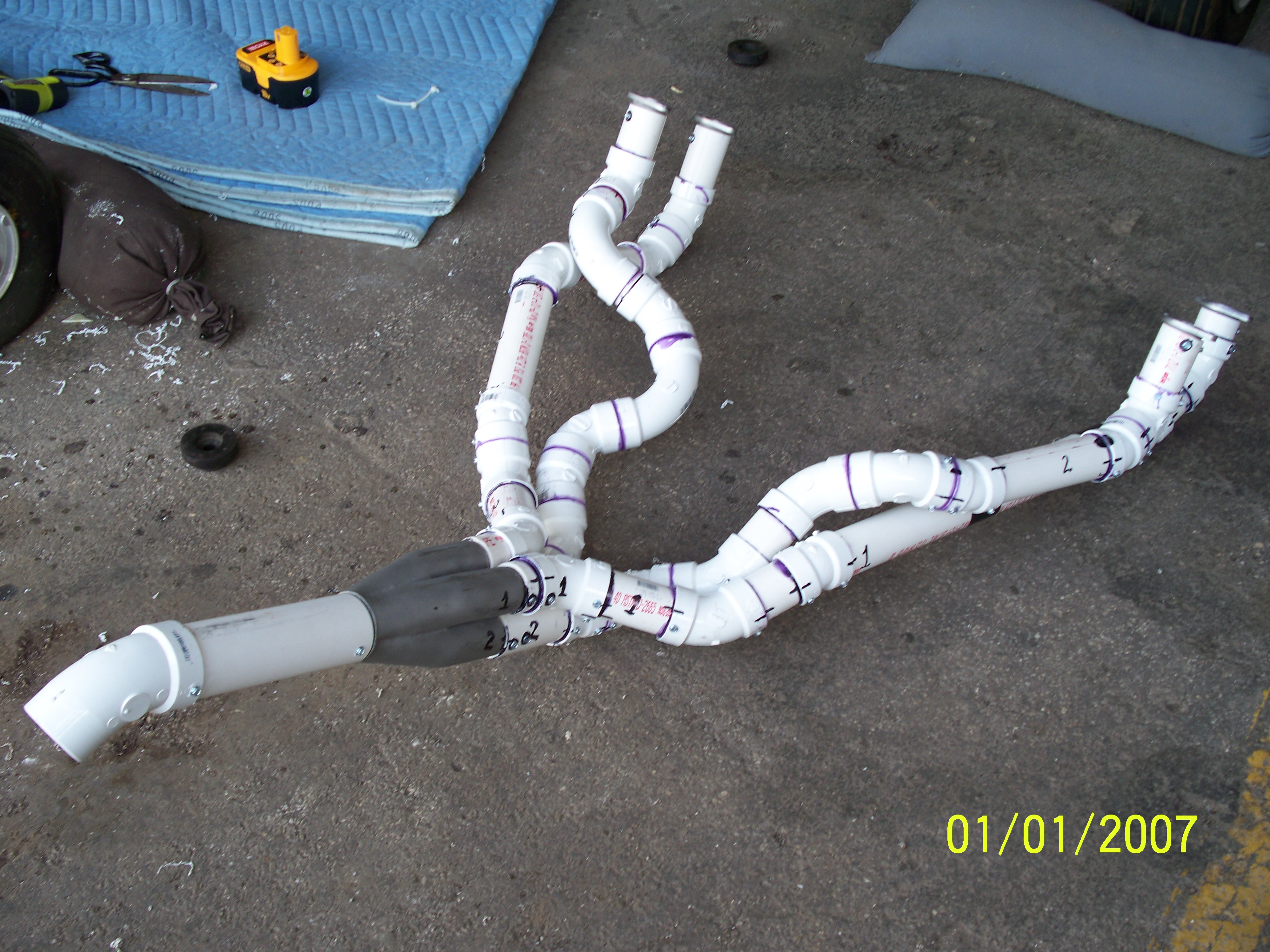
| The above is the completed mockup
before gluing all the componets together. |
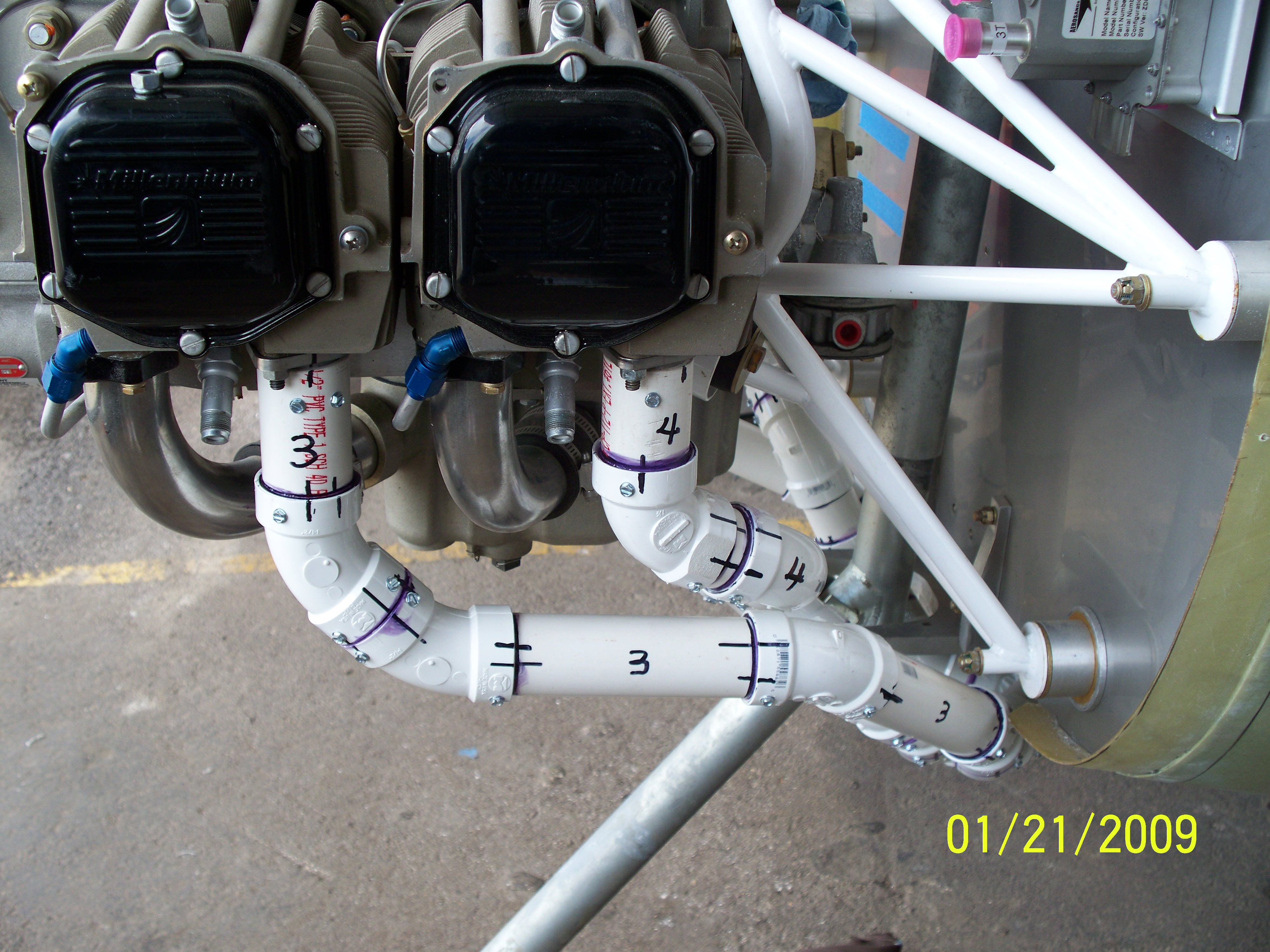
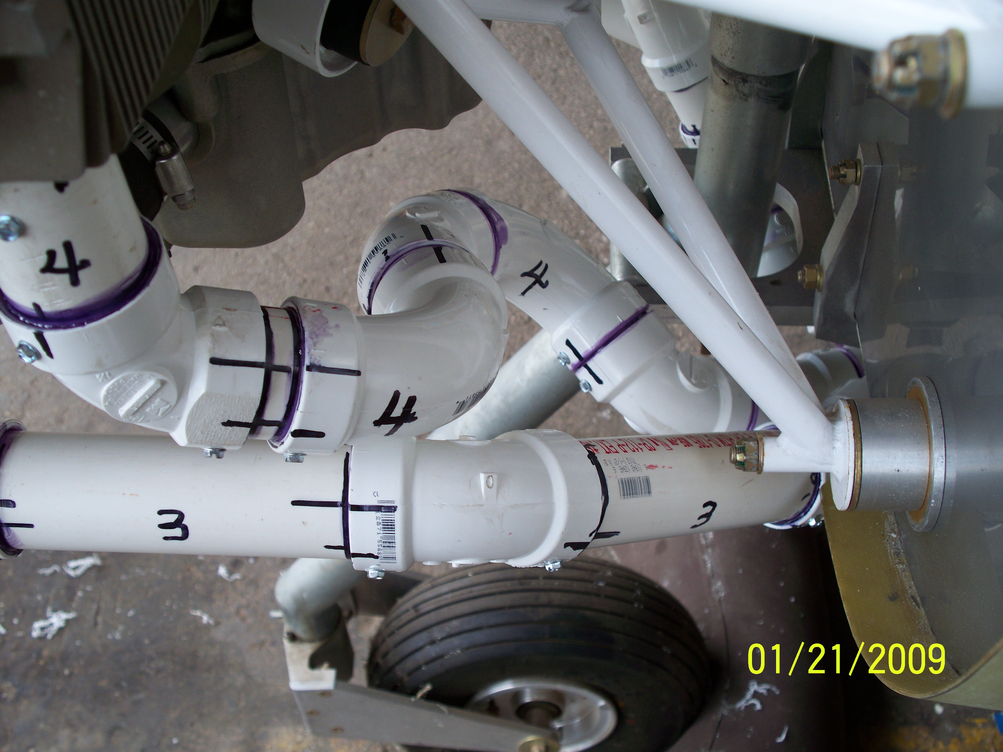
The length of the individual
exhaust pipes are all within 1 inch of each other. |
 |
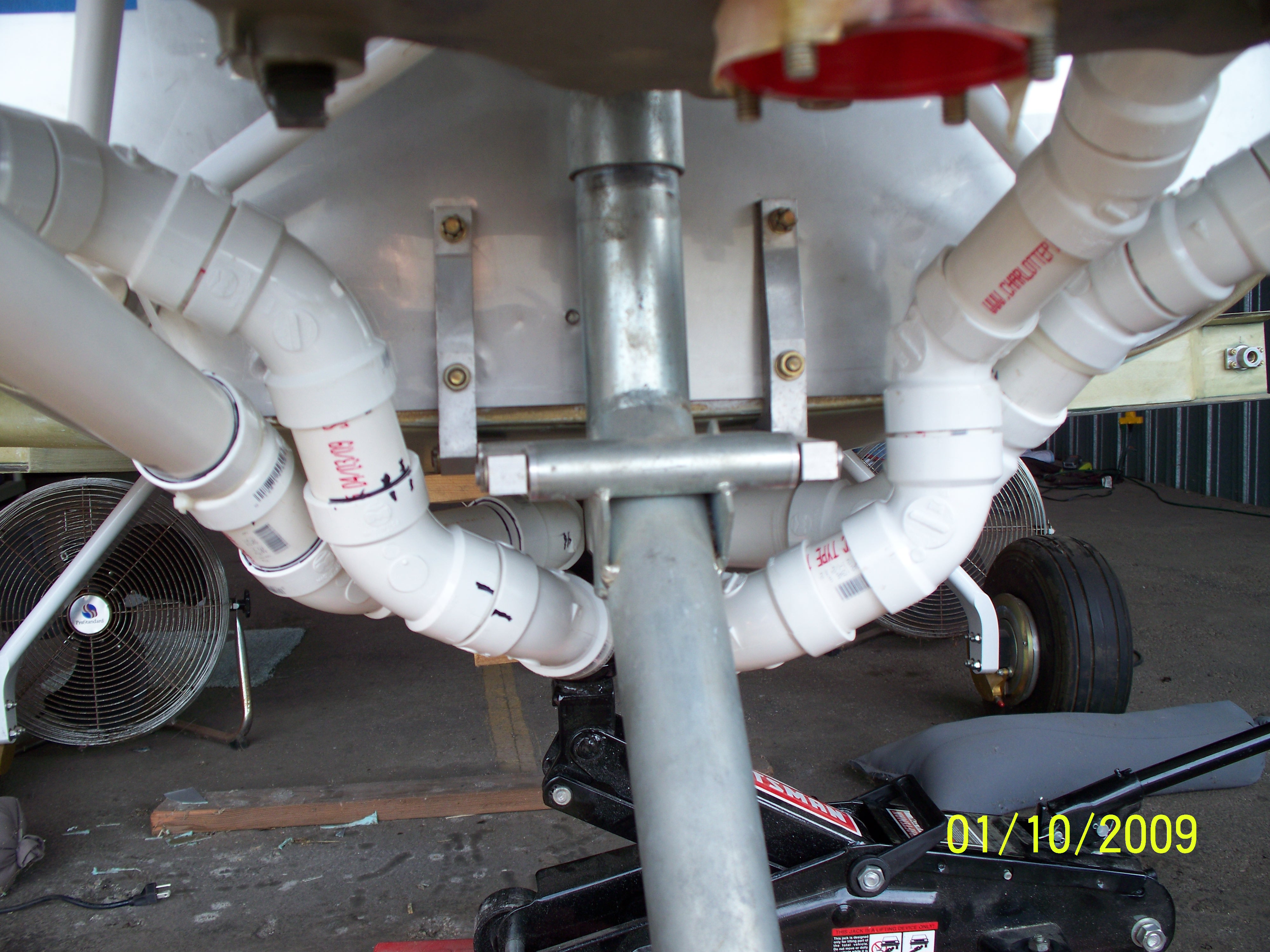 |
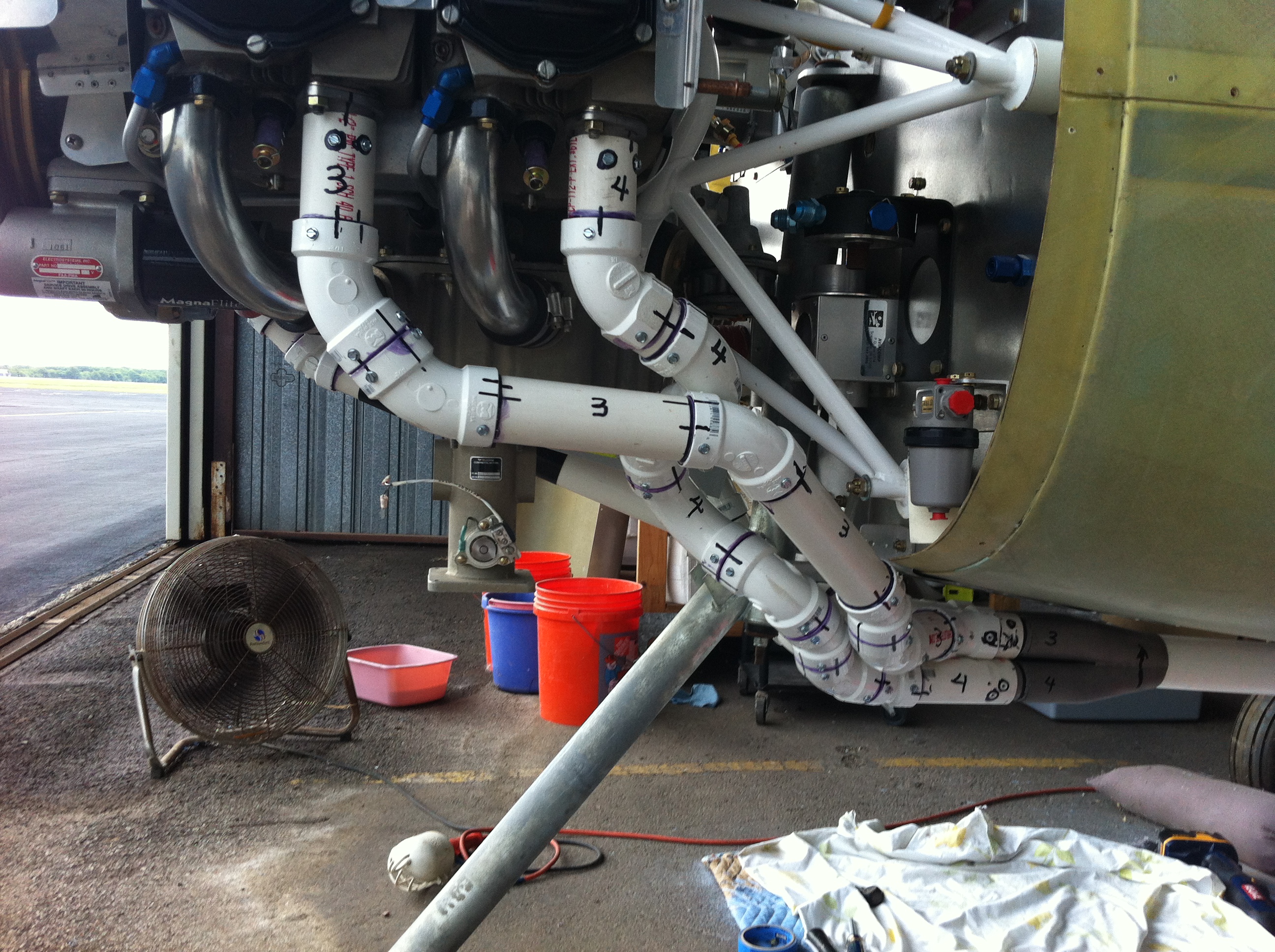
| The number 4 pipe takes several turns that don't appear to
be needed but are there to equalize the length. |
I had to assemble, disassemble, and rework several times
to
equalize the lengths. Time consuming and frustrating. |
|
|
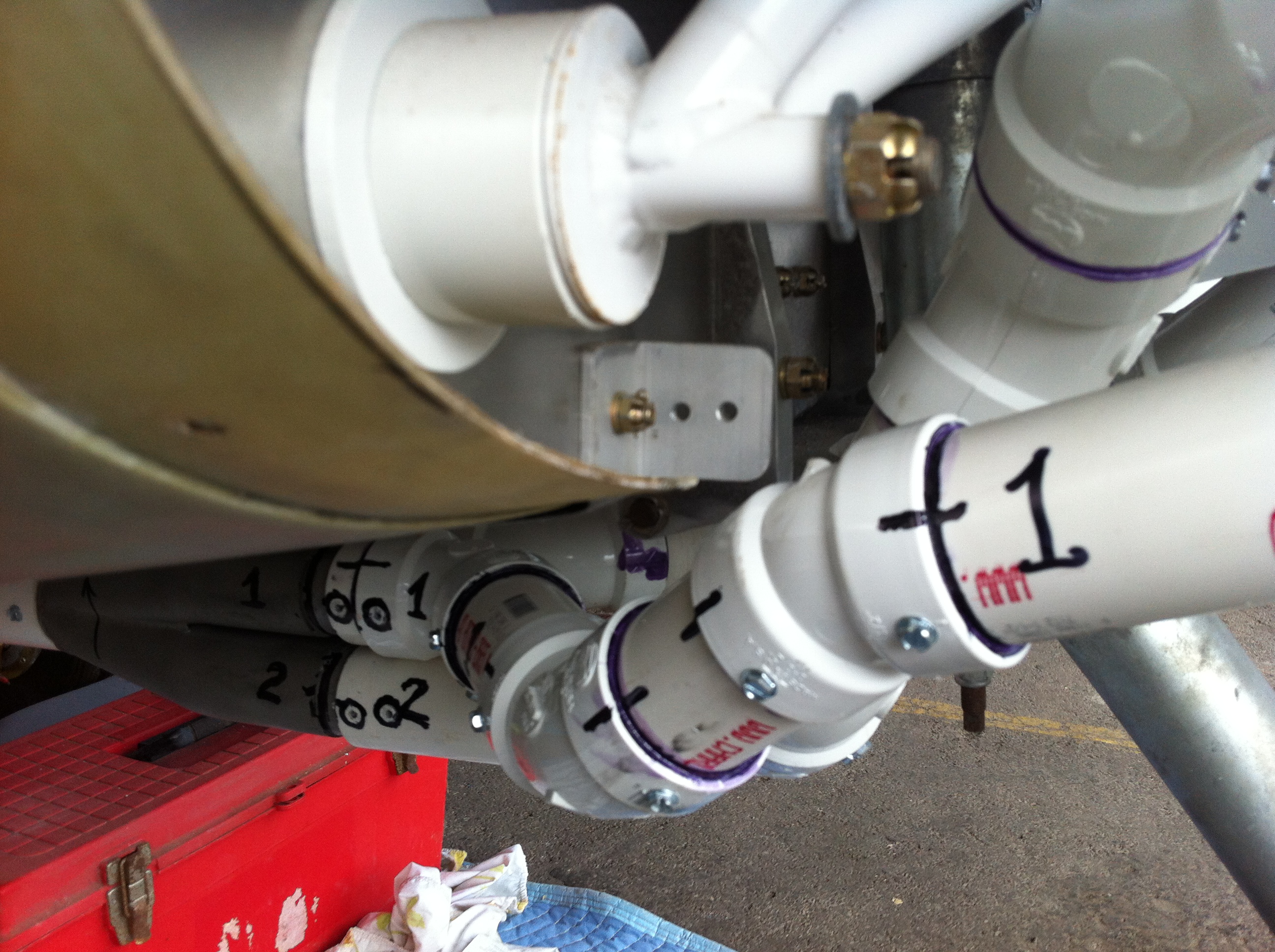
Once all the pieces were cut to the proper
length and dry fit into the collector they had to be marked to identify
how they went to gether and which pipe was which. The entire
system would then have to be disassembled yet again. Each piple
would then be reassembled using PVC Cement and screws to lock all the
pieces into their proper position for shipment. Once everything
was glued into place it was fully assembled again to make sure
everything fit as designed.
|
 |
 |
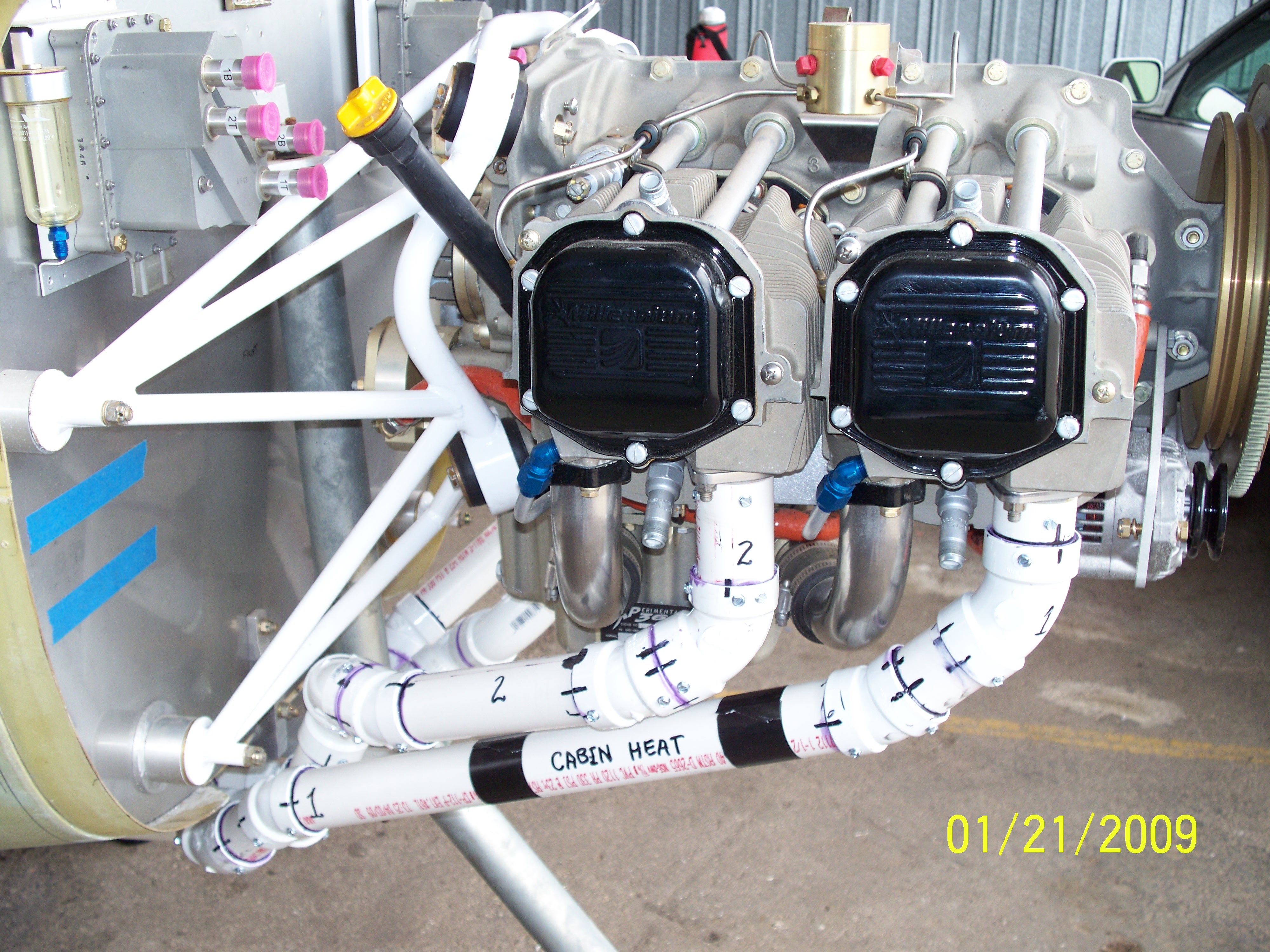
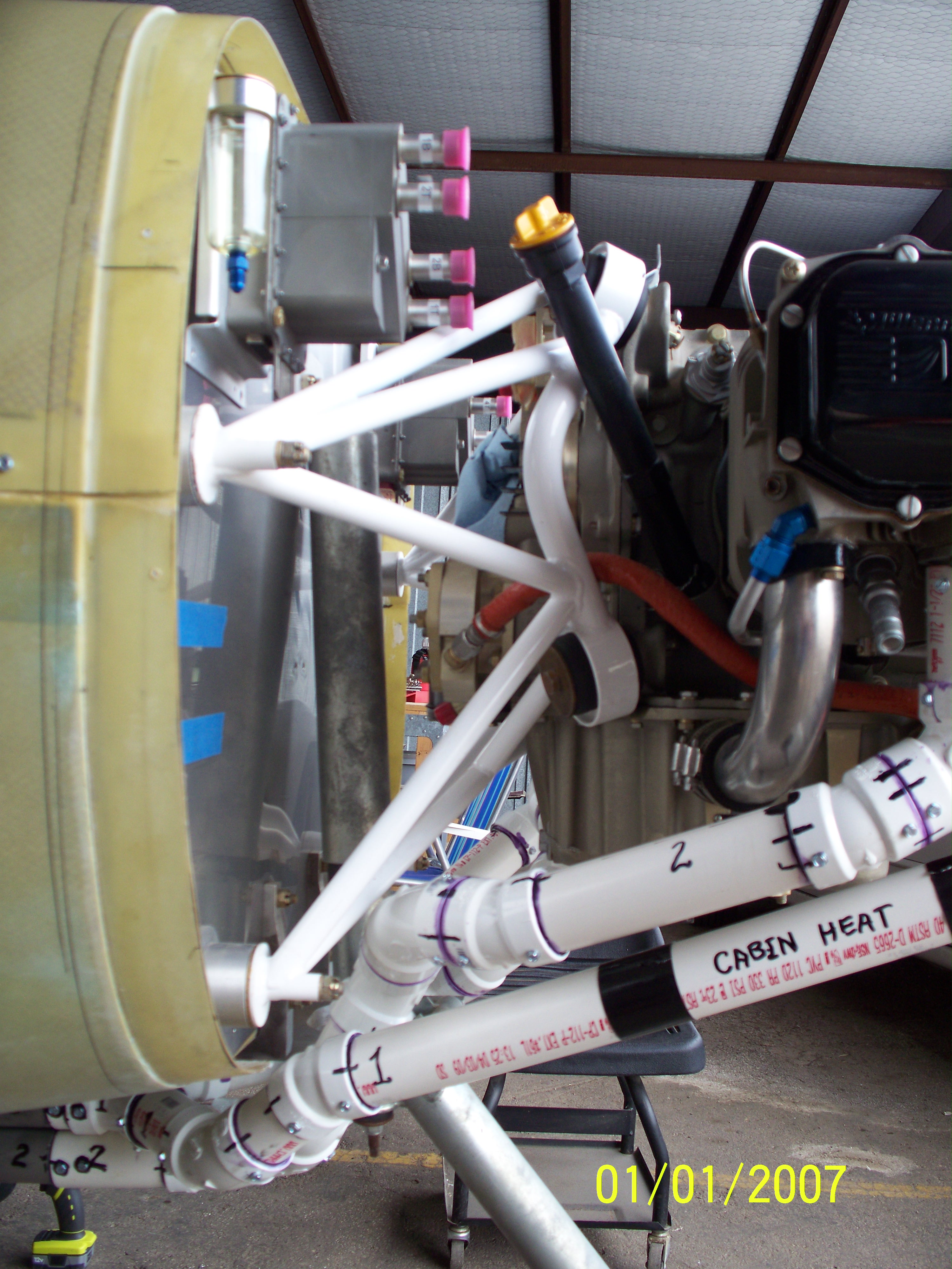
| The heat muff for cabin heat
will go where shown. |
If needed, carb heat could be
place on the other side. |
 |
 |
 |
 |
 |
 |
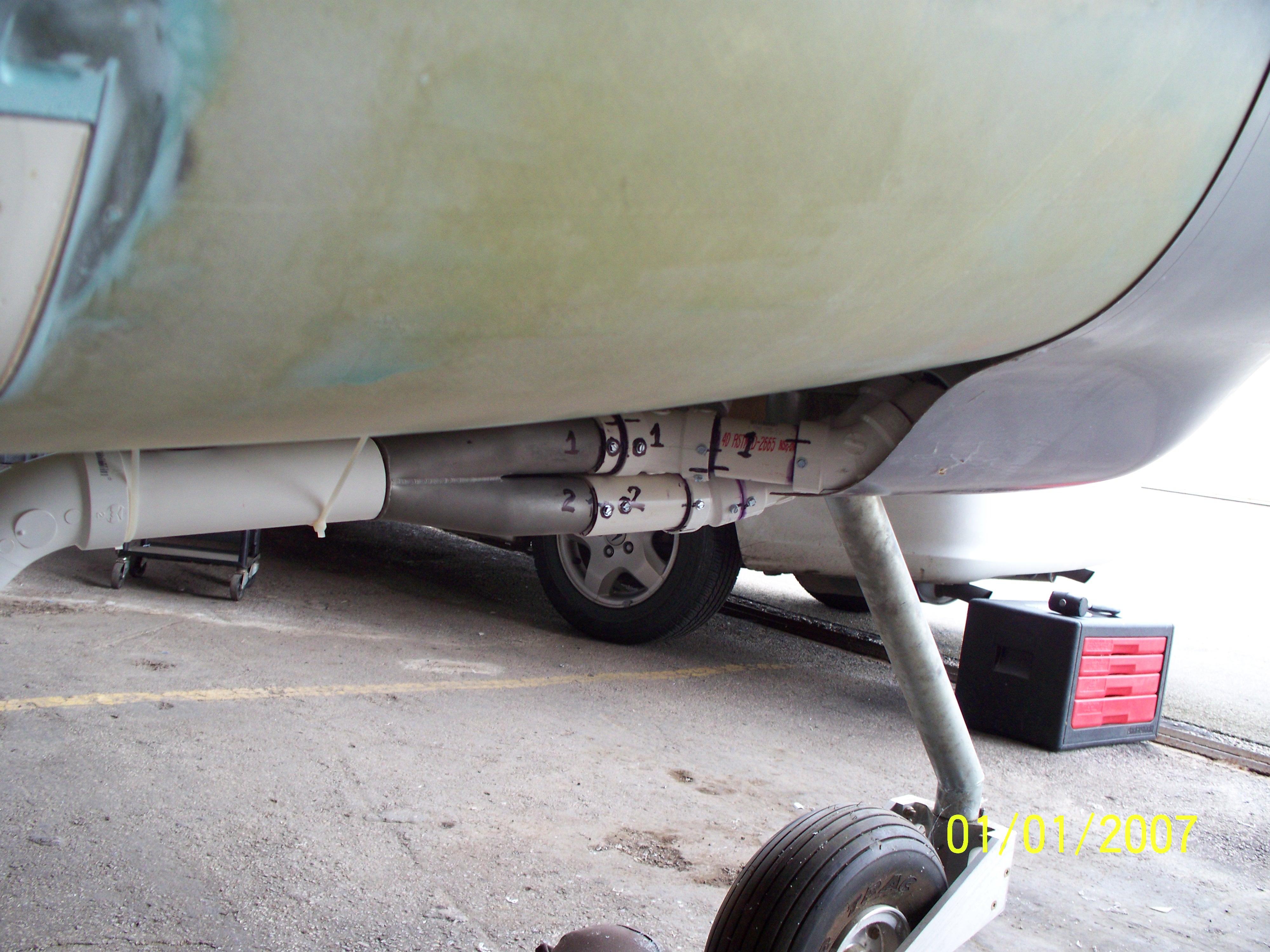
The underside of the fuselage along the Center will have a
stainless steel panel with fiberfax backing installed. |
The fuselage panel will protect the fuselage from any
exhaust heat.
|
 |
 |
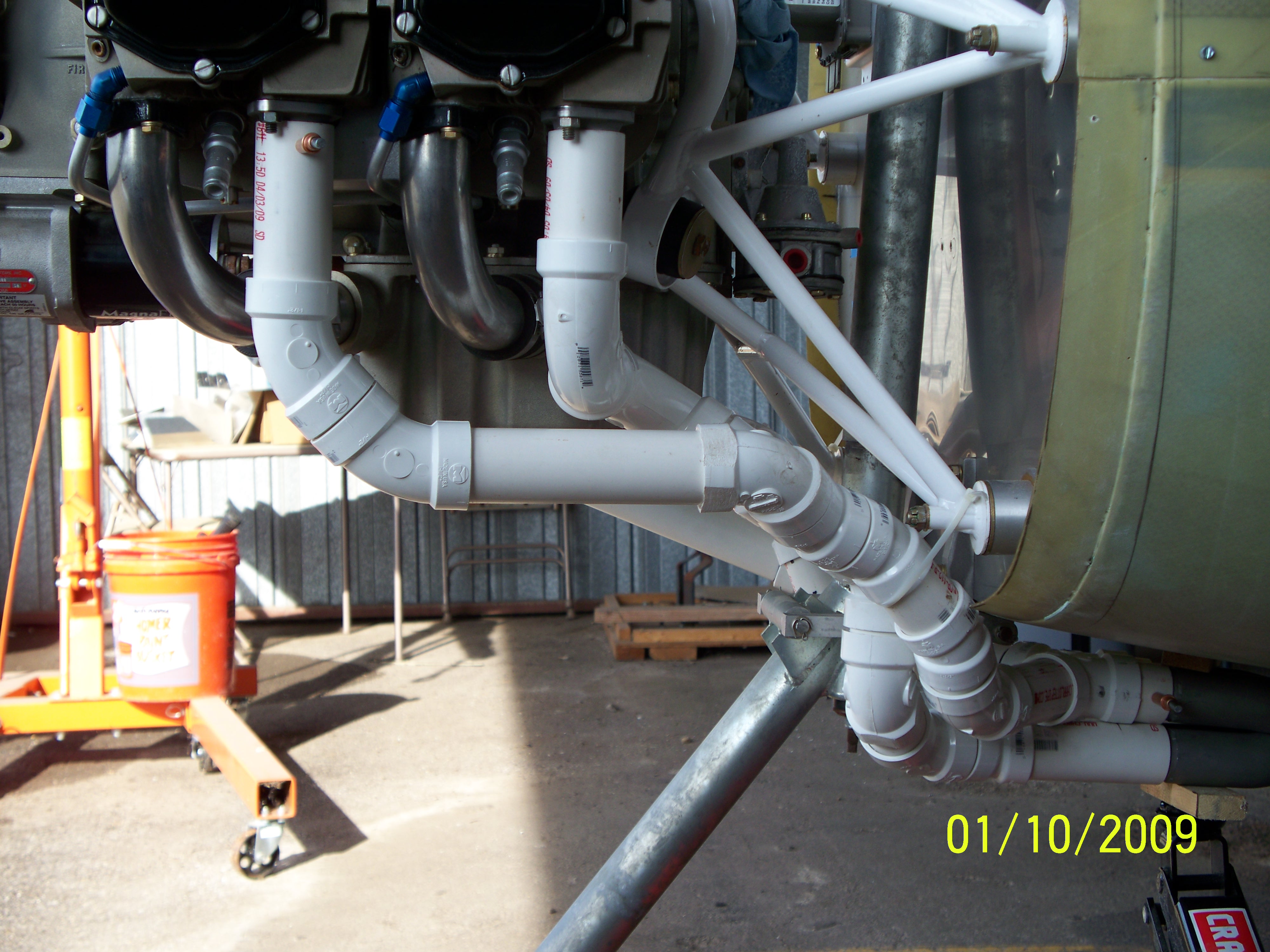
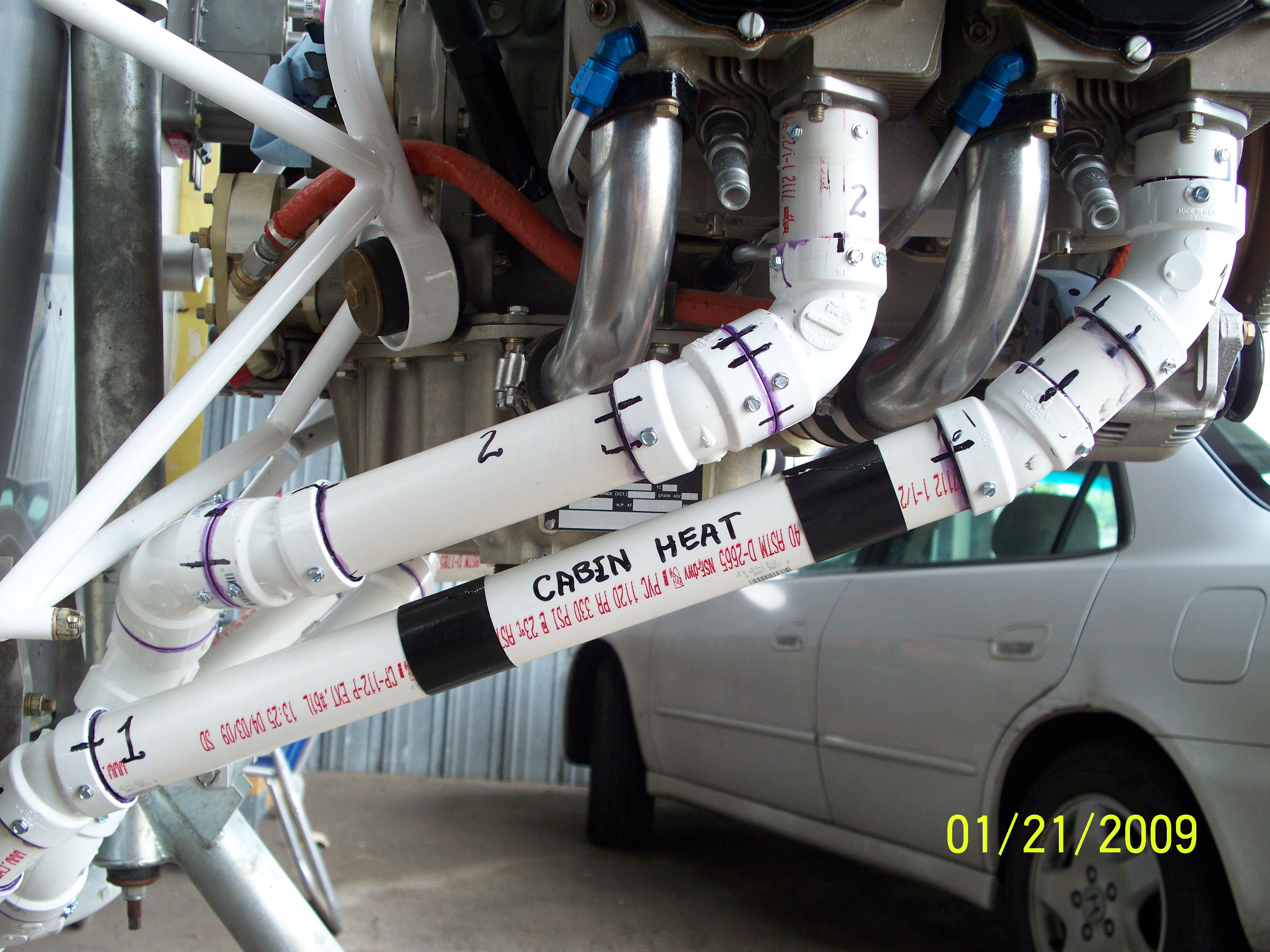
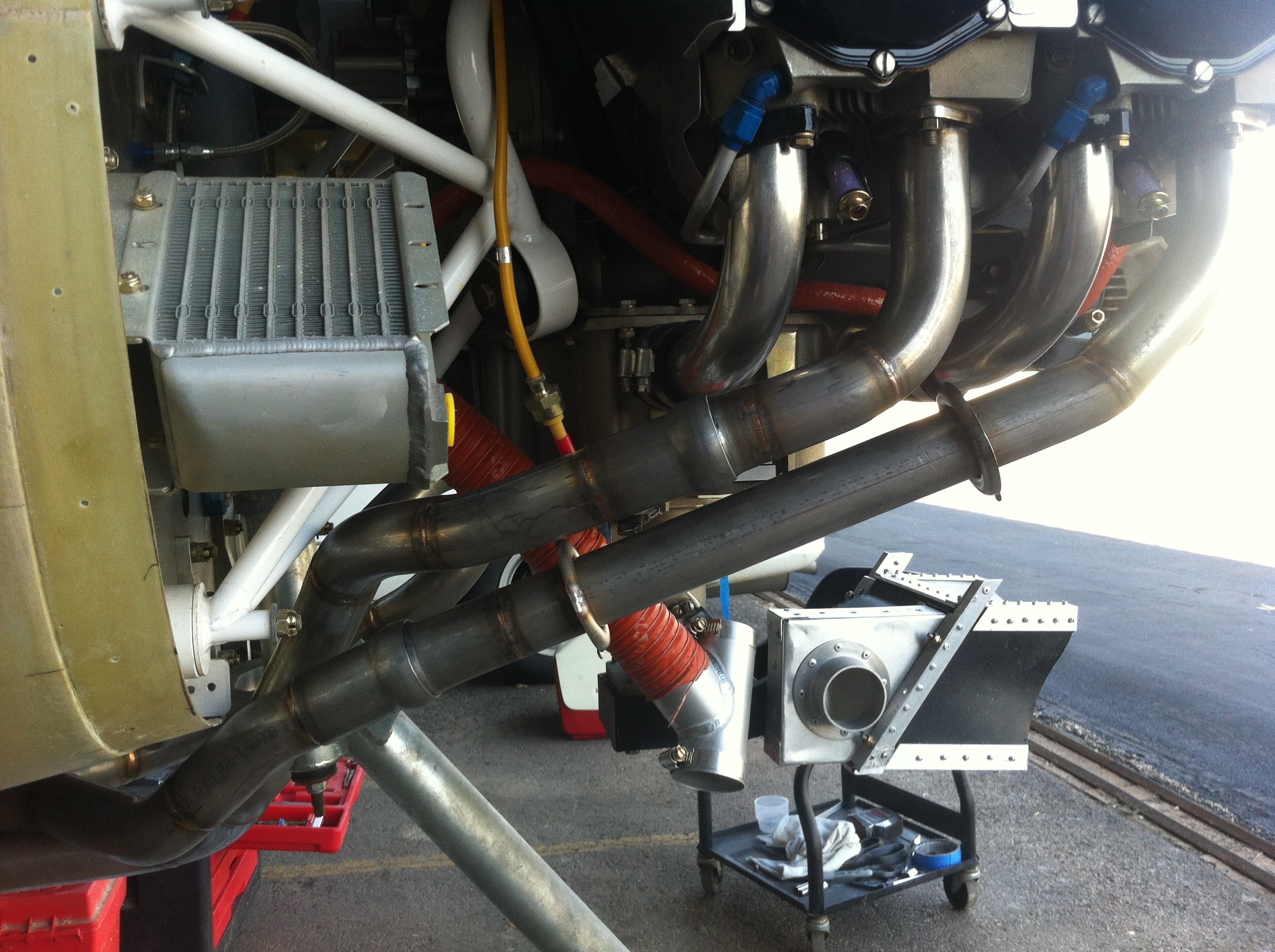
Care must be taken to ensure clearance between exhaust
components and anything that might damage them. |
Or any components which might be damaged by the hot exhaust
pipes. |
|
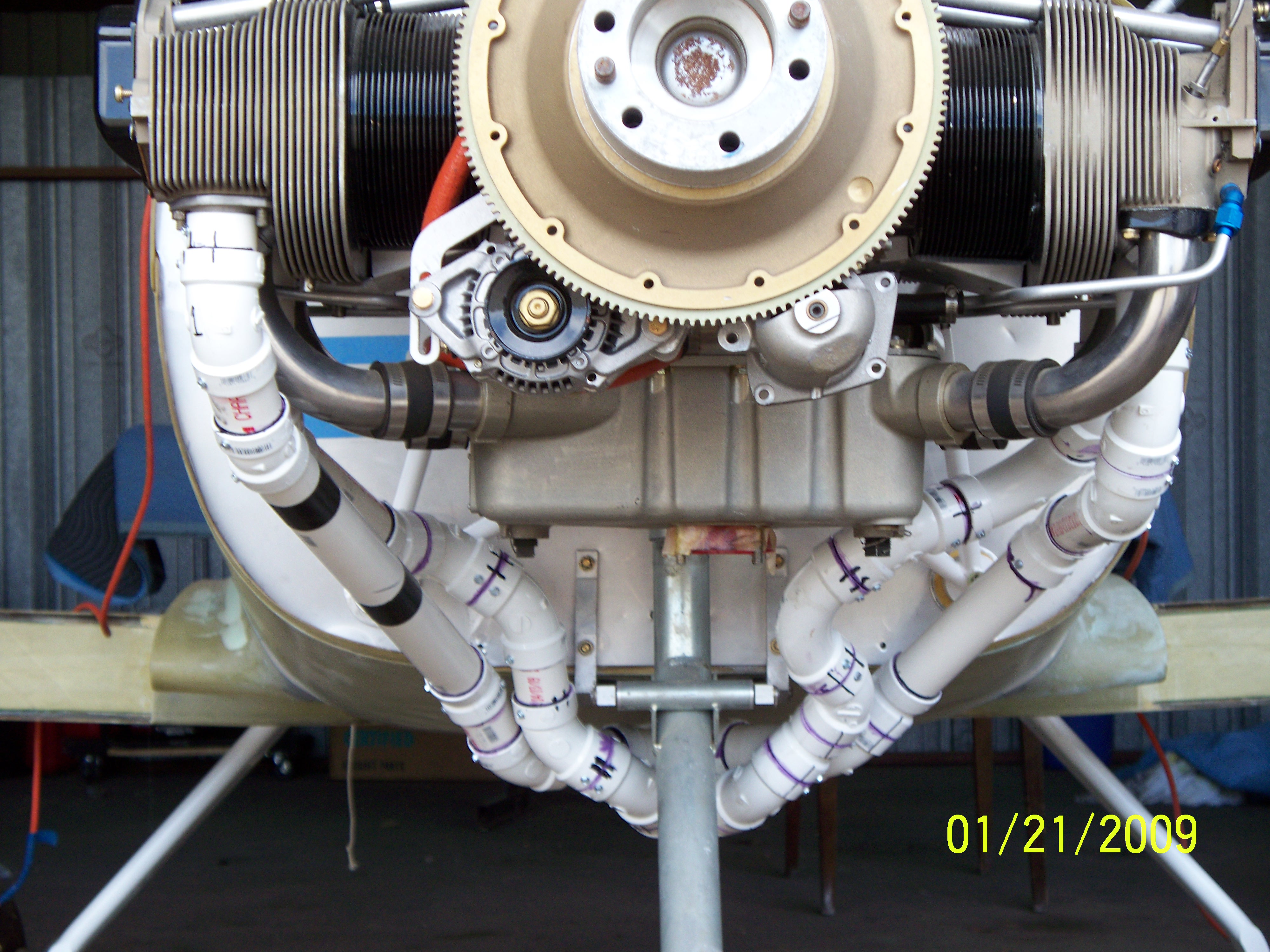
|
 |
 |
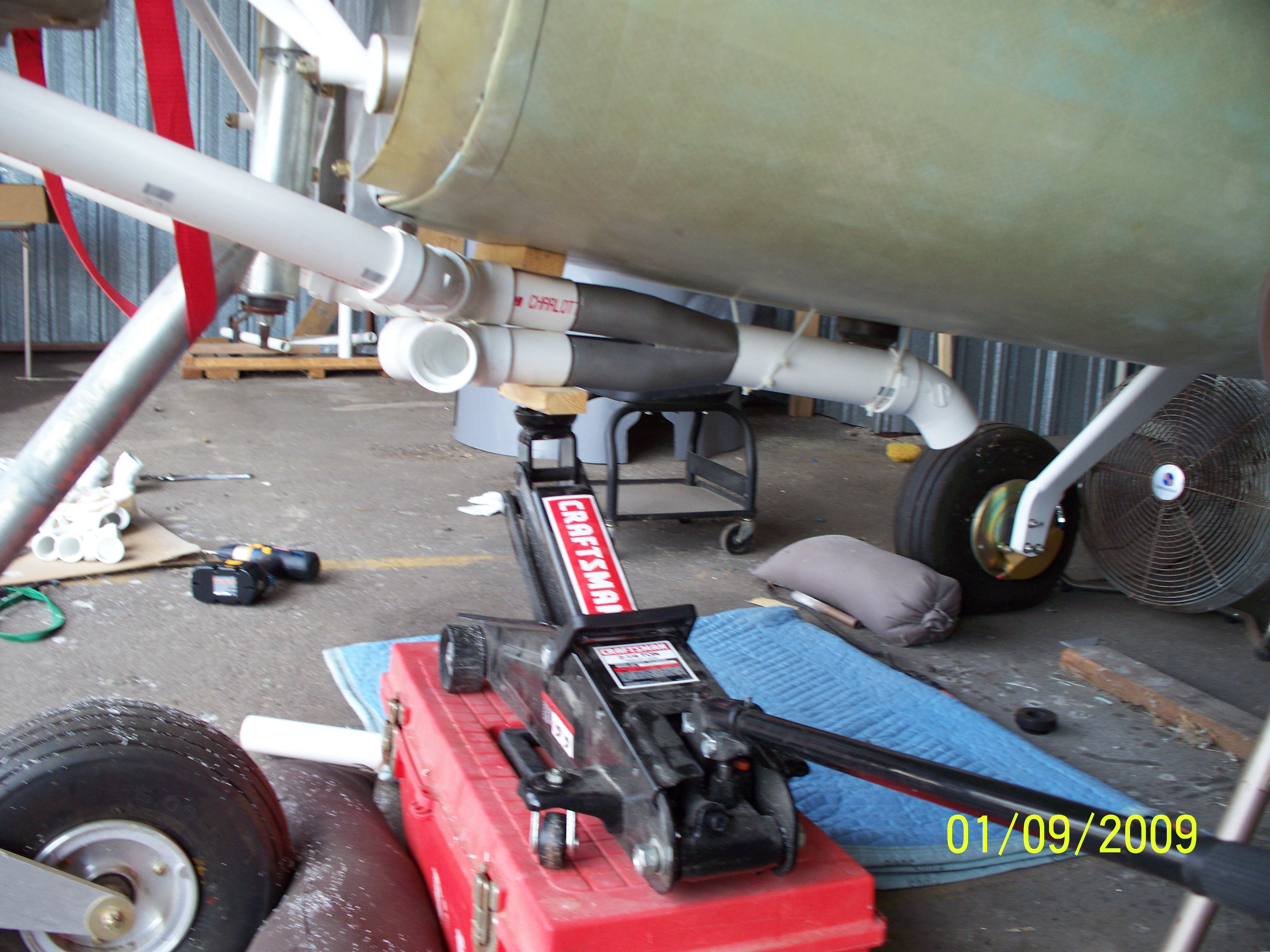
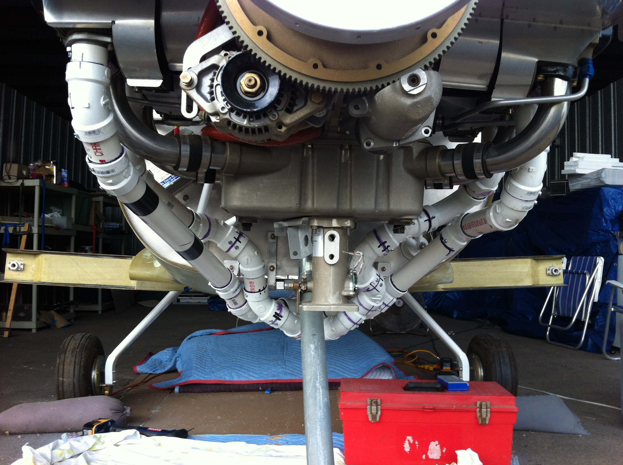
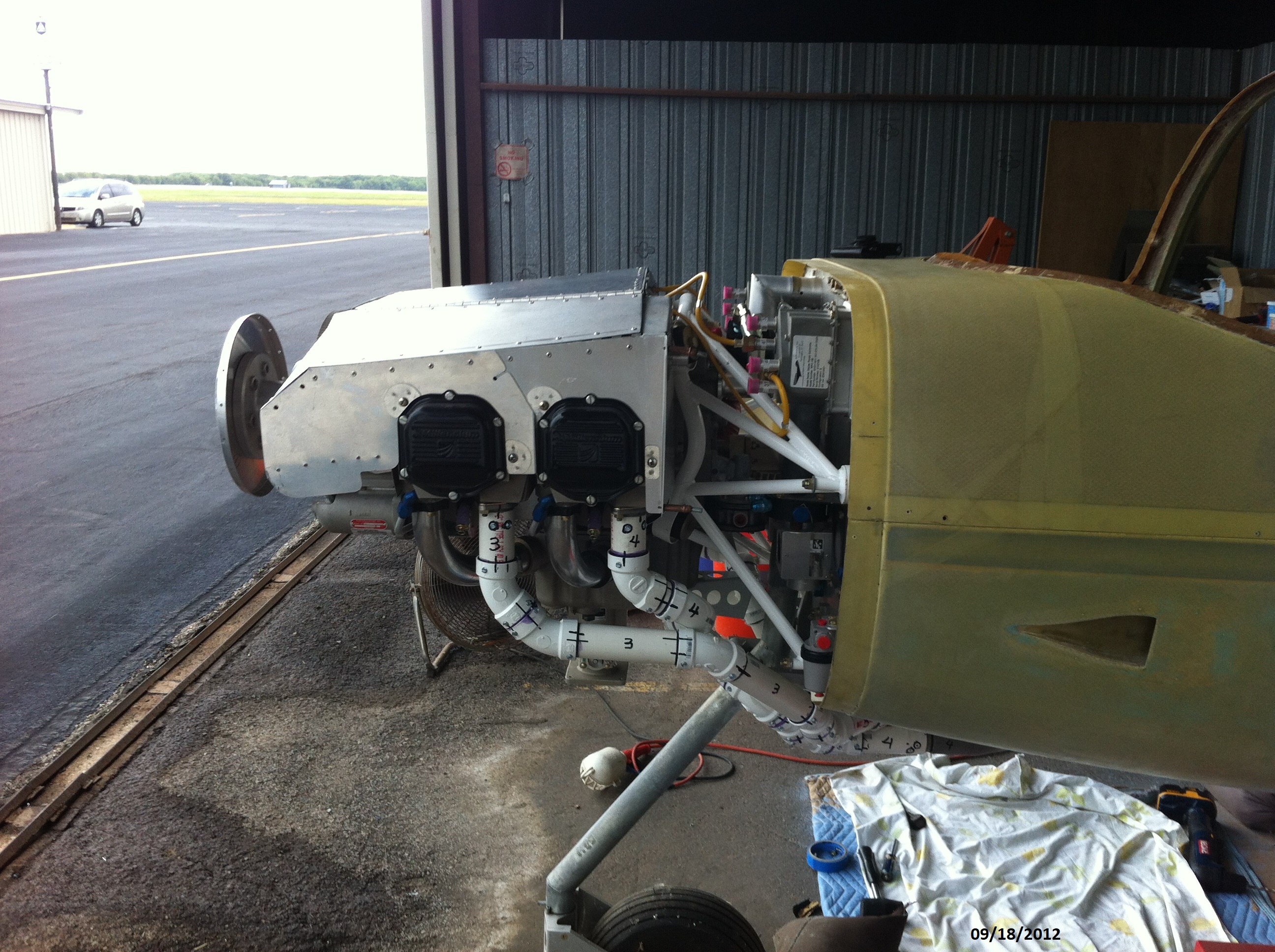
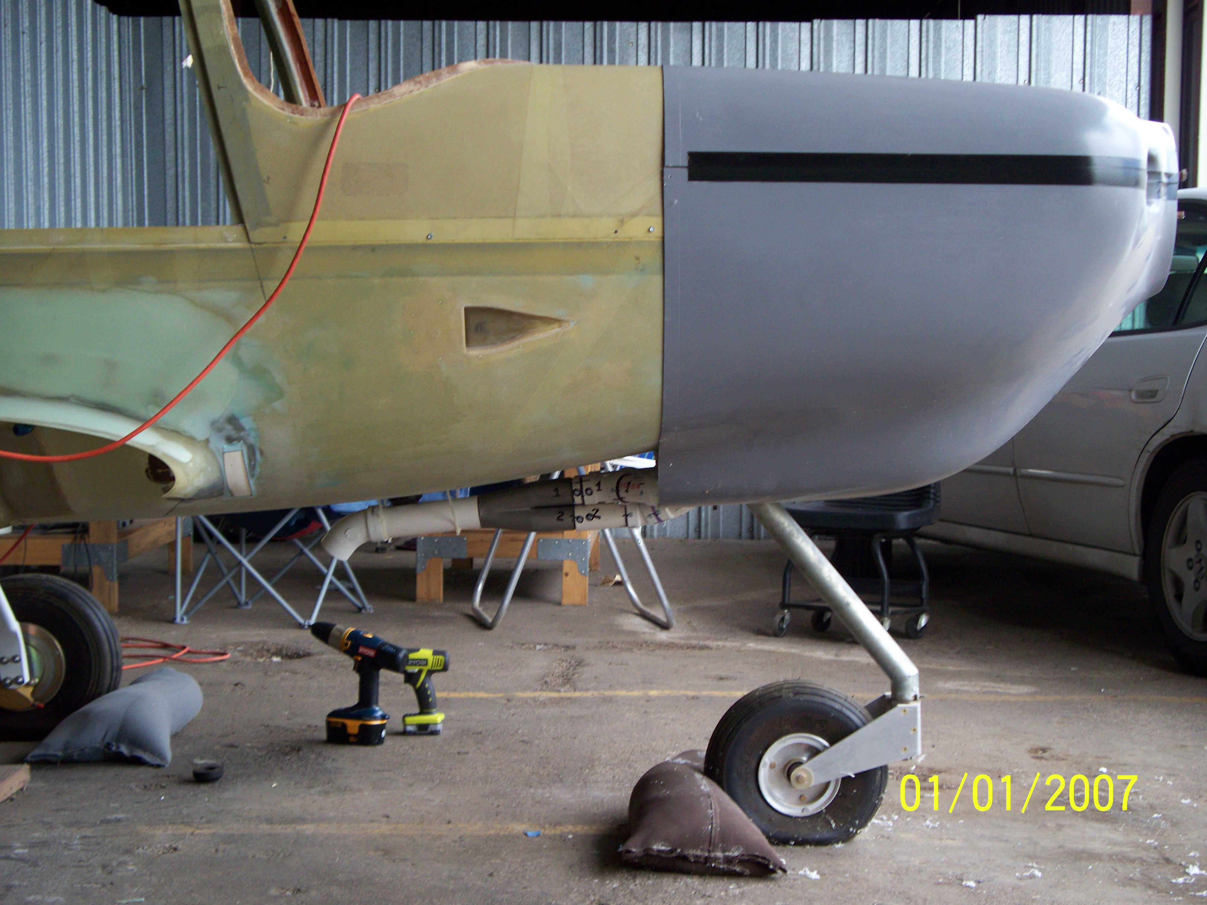
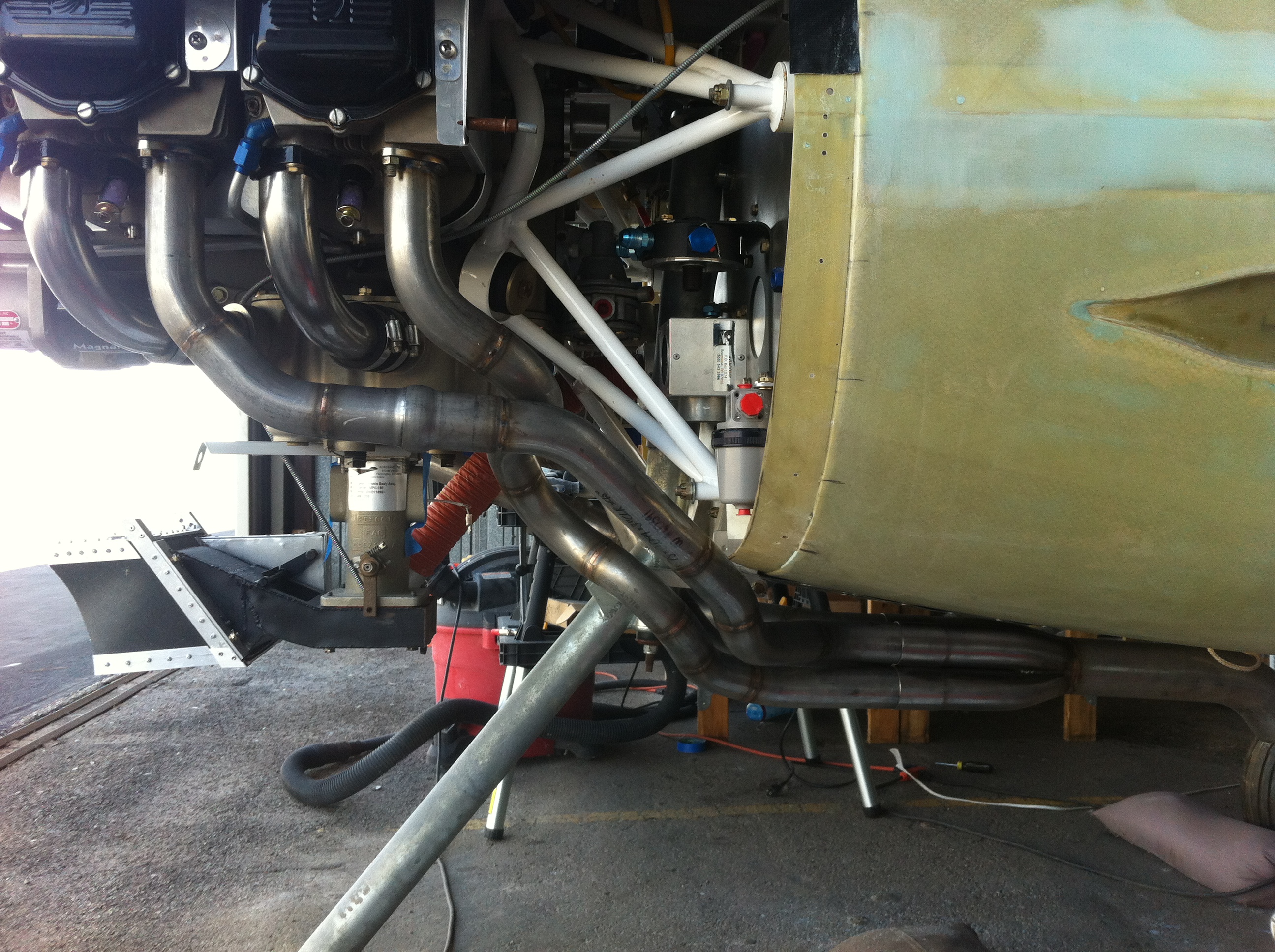
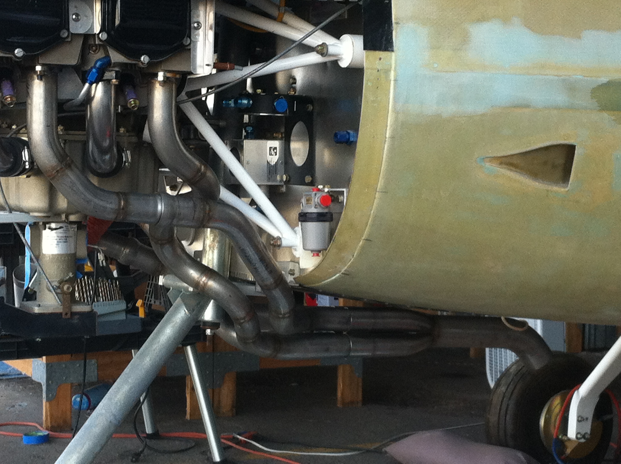
The above show the
routing of the system between the engine and the underside of the plane.
|
 |
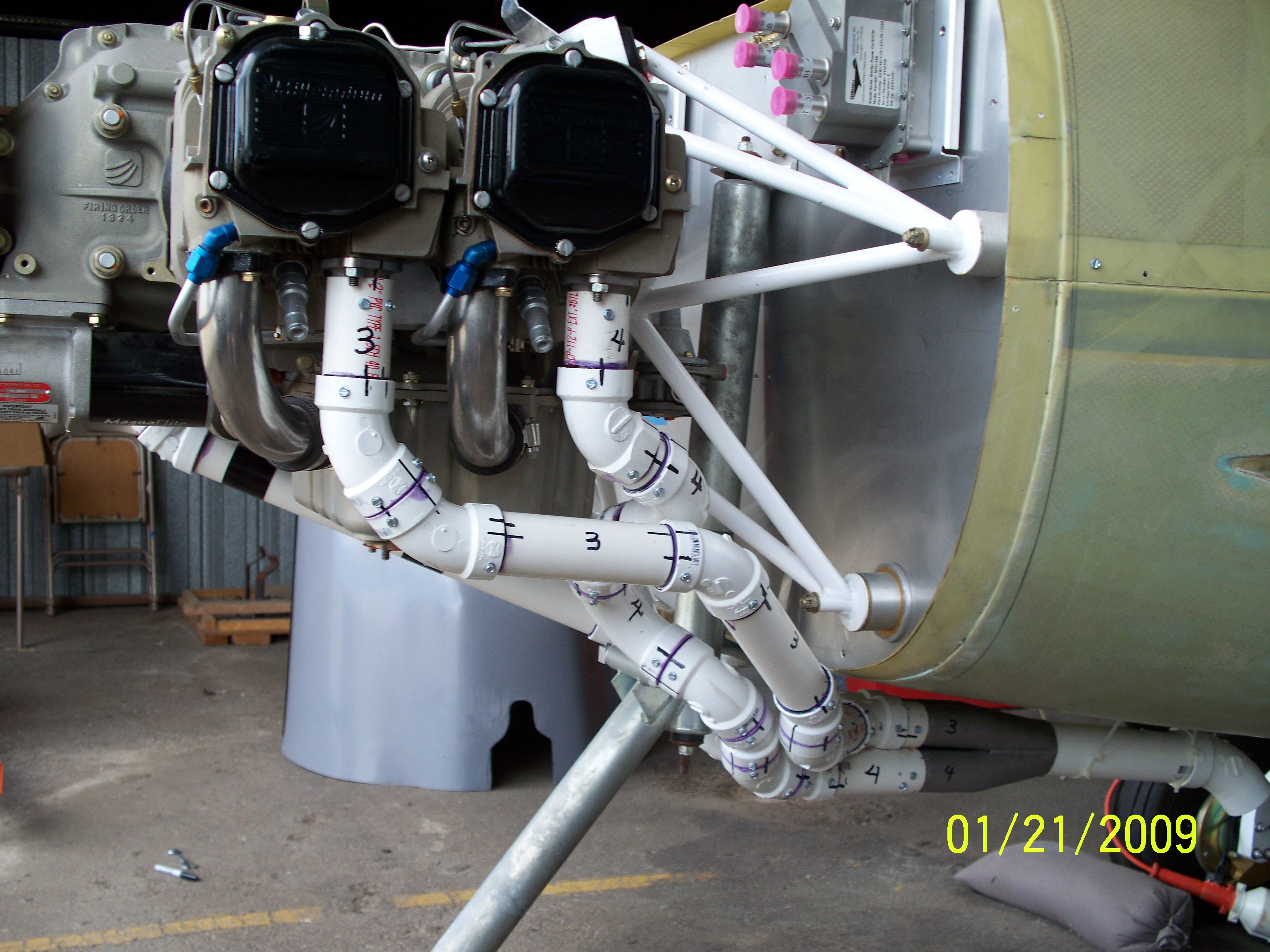
 |
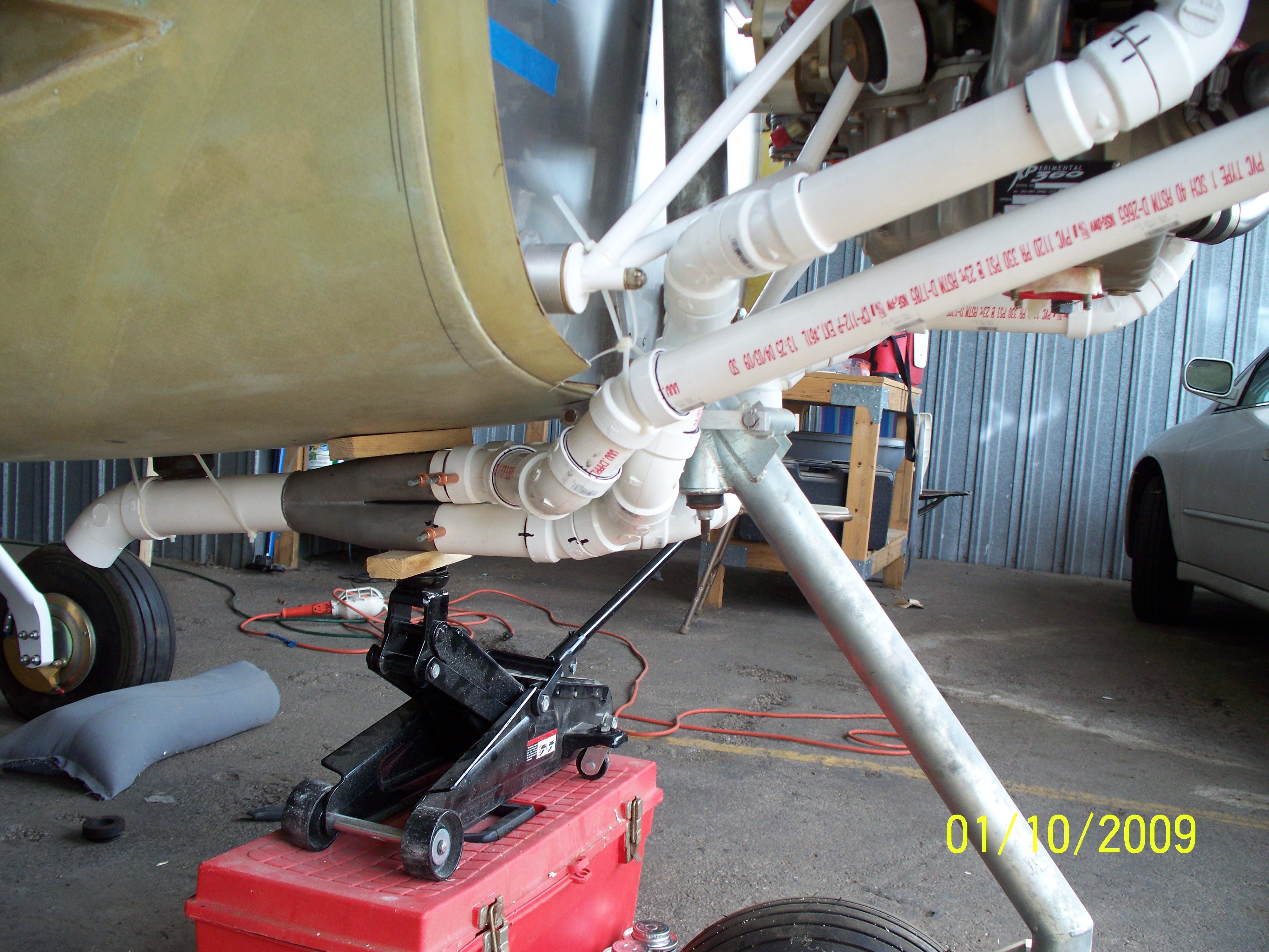
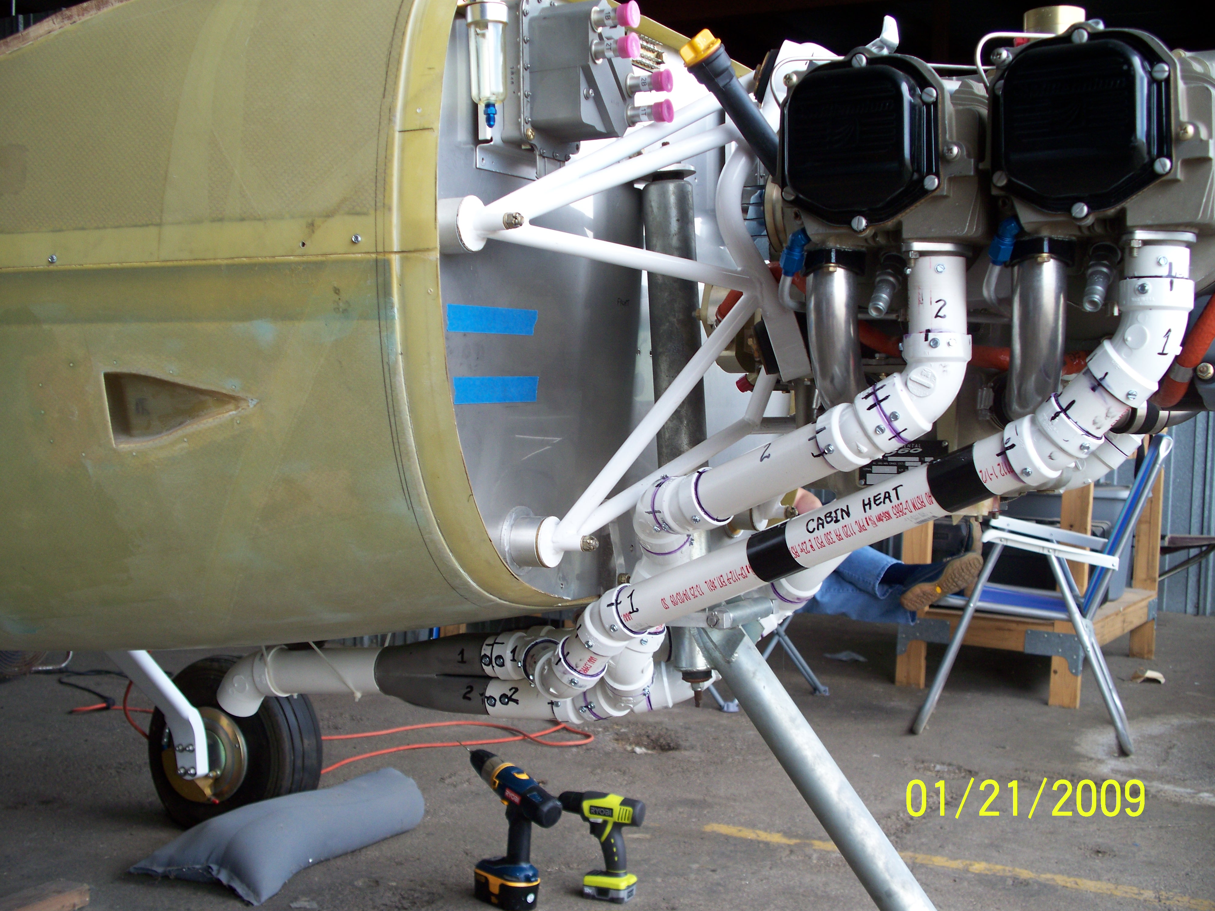
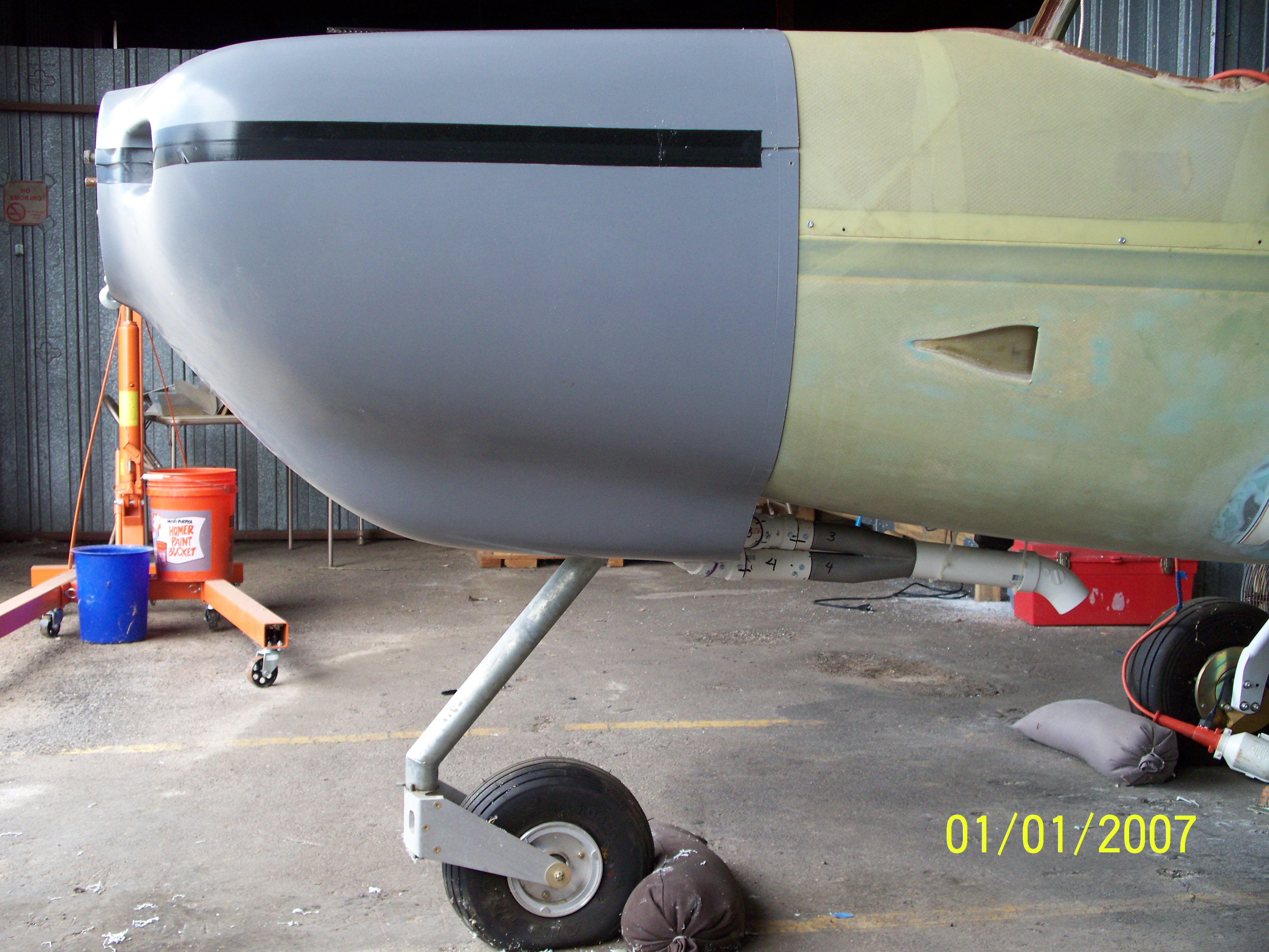
| The view from the side shows how closely the cowling fits
and how far back the full system will go. |
Some adjustments will be needed to the cowling to provide
more space from the exhaust pipes. |
 |
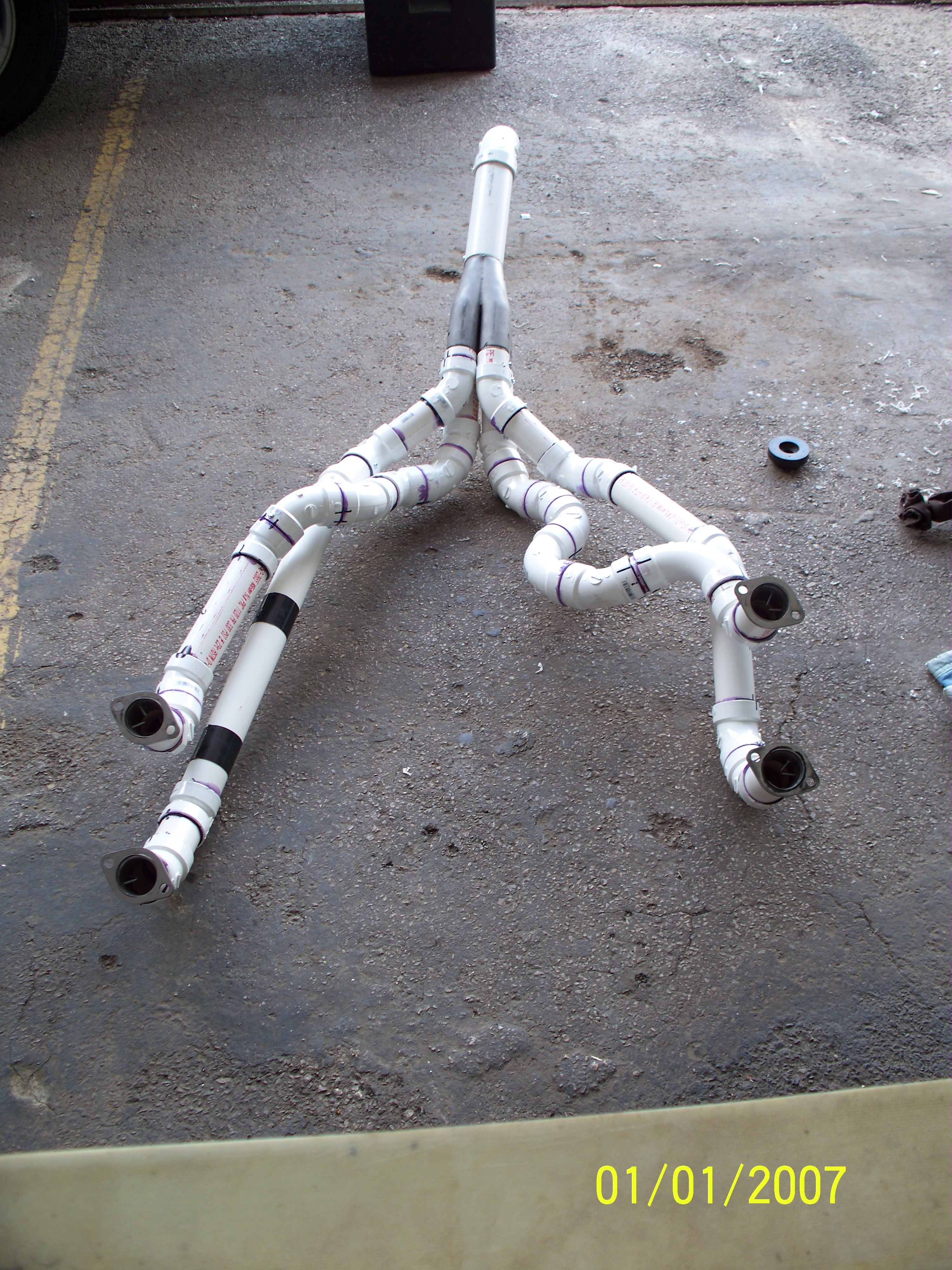 |
The completed mockup is glued together and ready to be
disassembled at the collector for shipment. |
When removed from the engine, the mockup retains its shape
exactly as formed. |
 |
 |
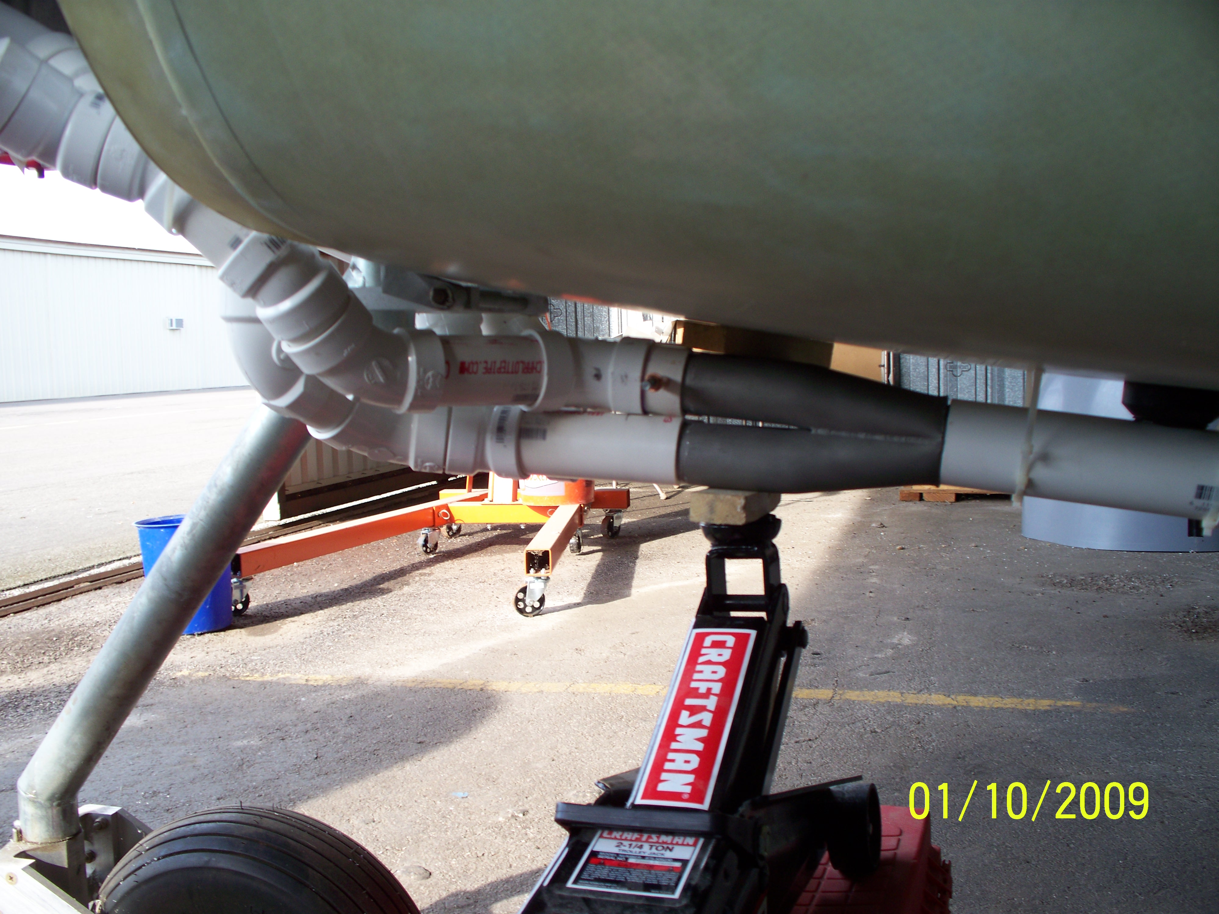
I was concerned having a large portion of the HOT exhaust
system under the fuselage and what effect that head might
have on the Fiberglass structure. |
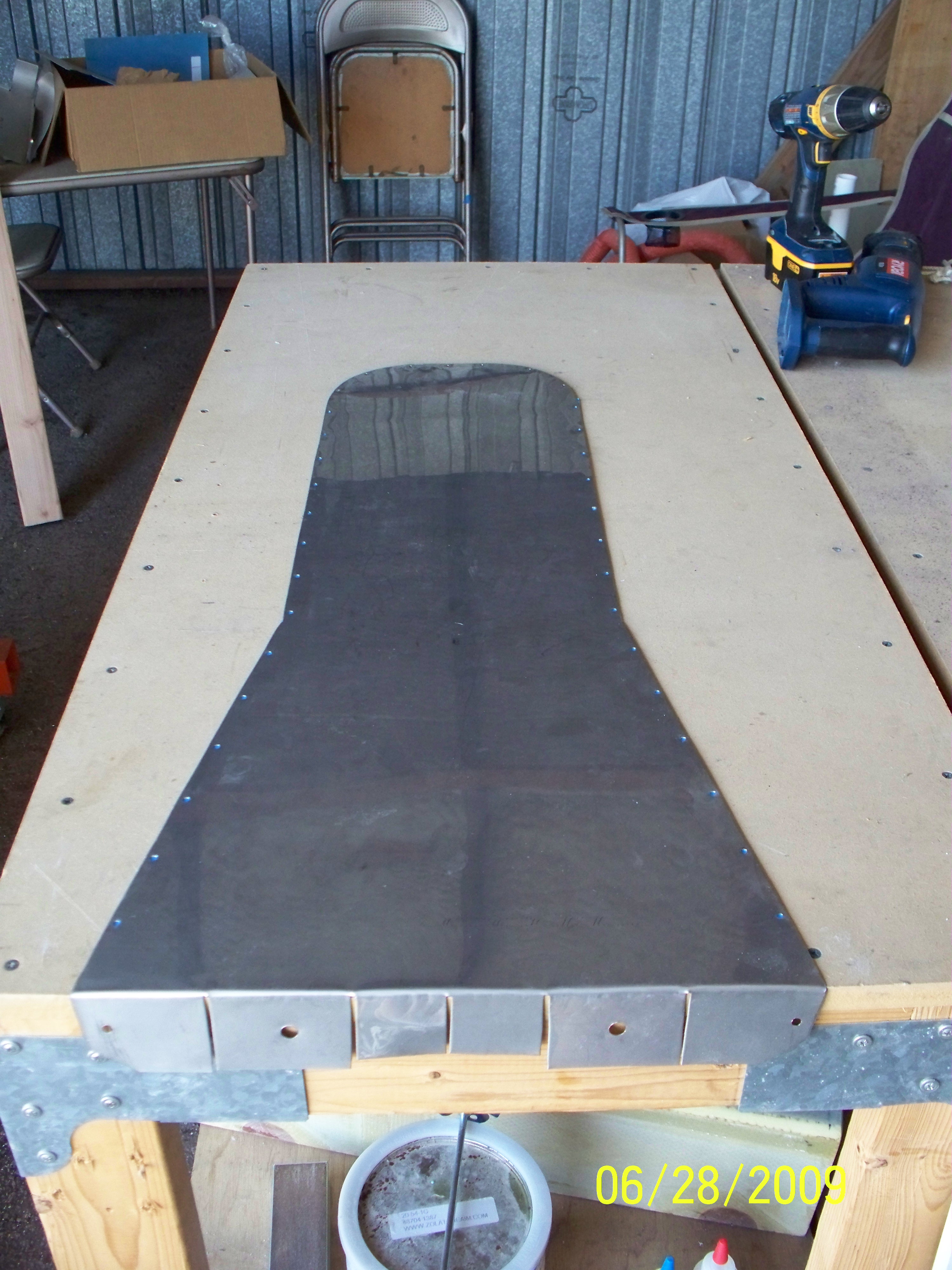
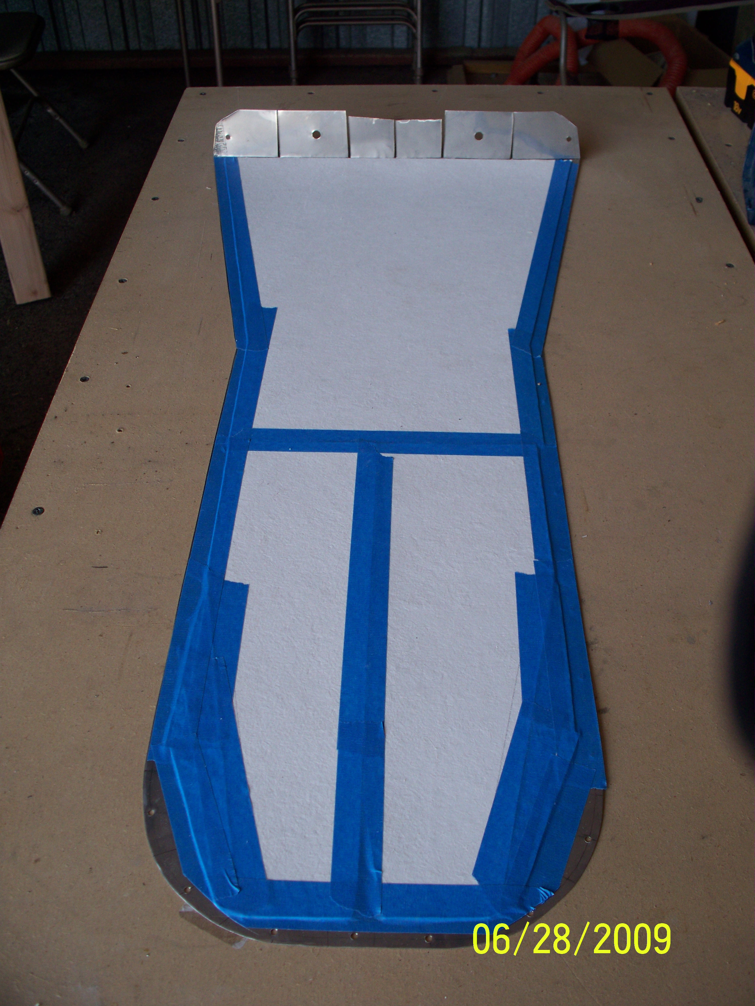
My solution was to fabricate a protective belly pan from
the same stainless steel material used for the firewall. I also
lined it with the fiberfax used on the firewall. The tape just
holds it in place. |
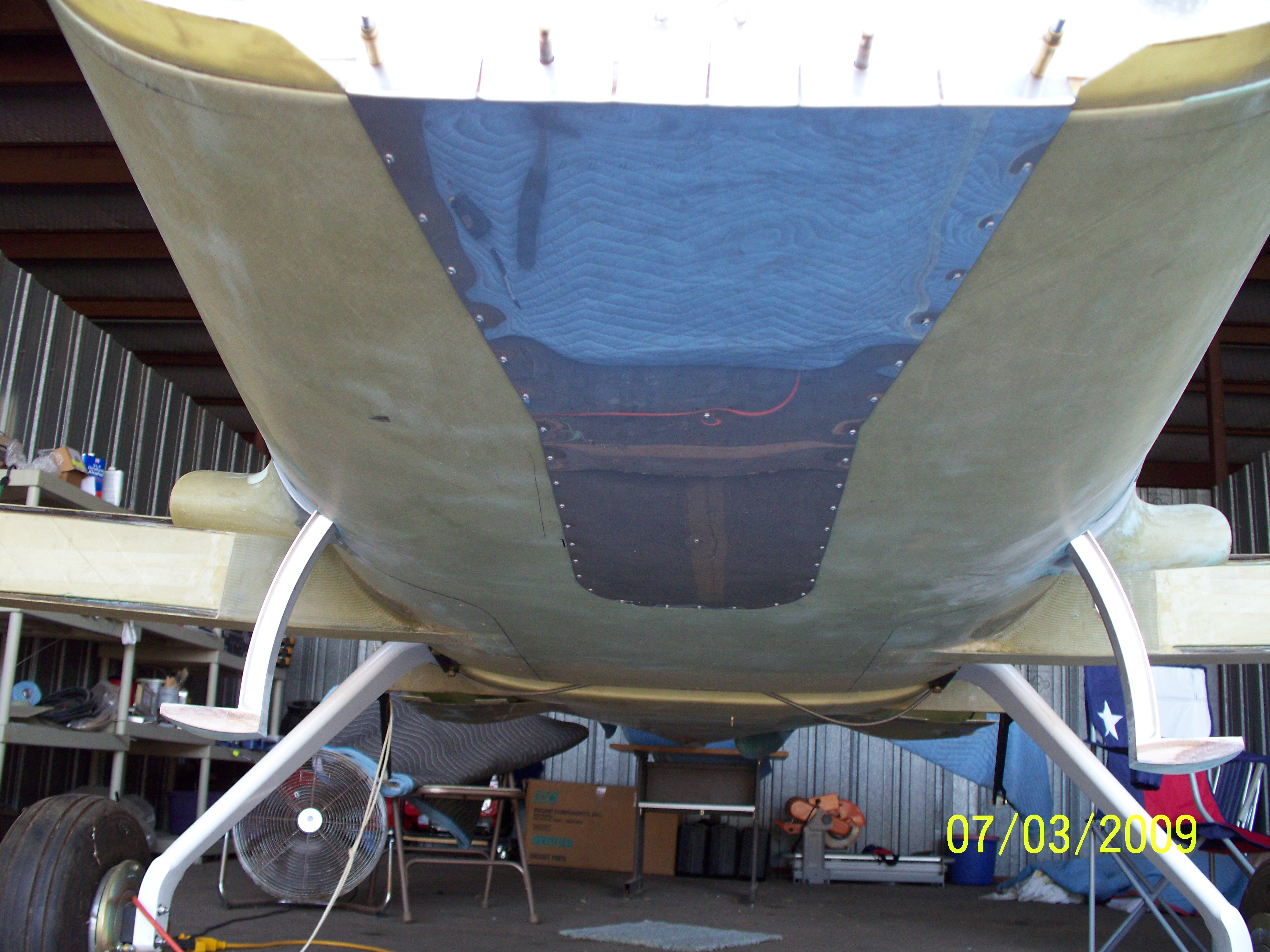 |
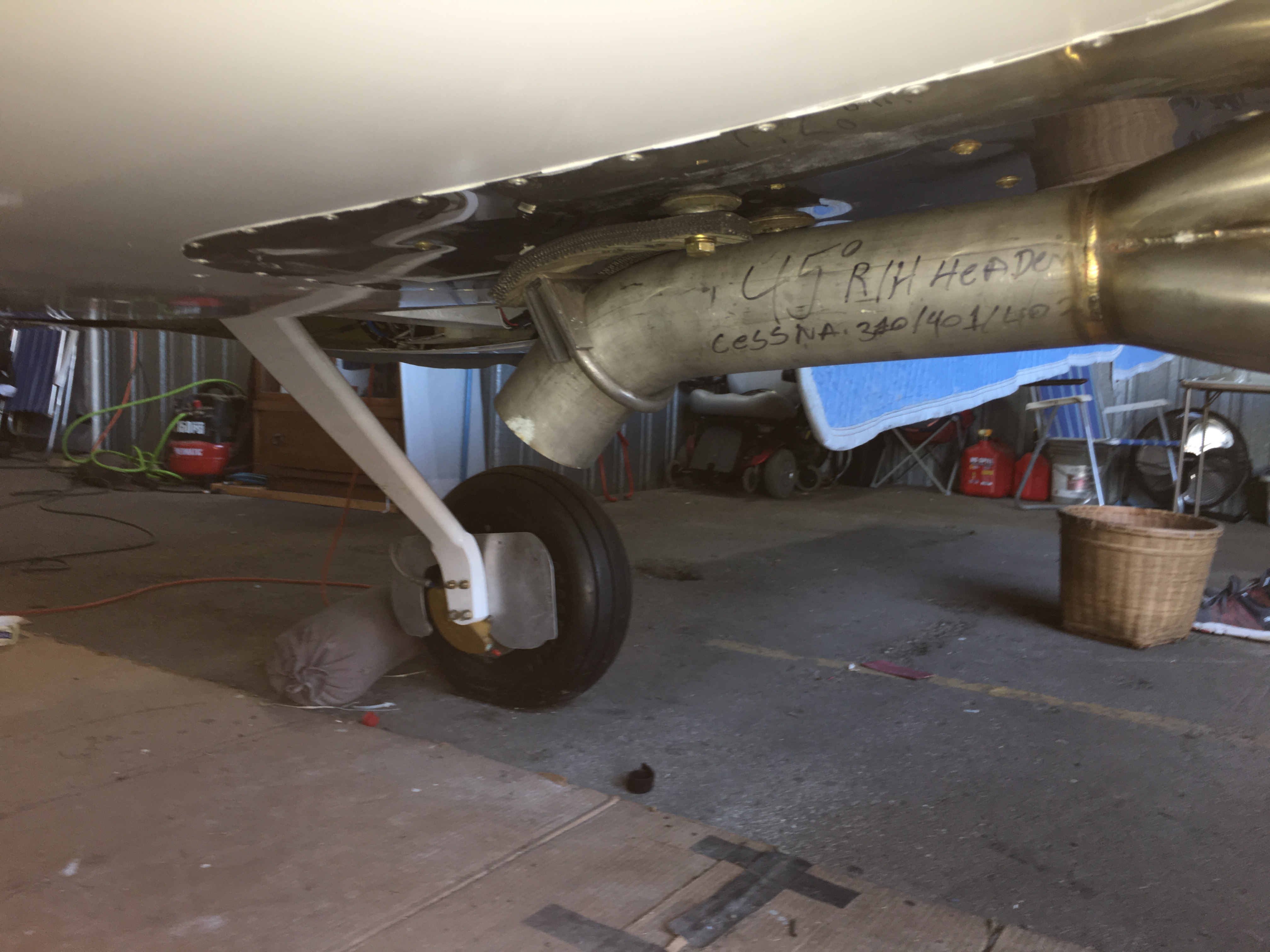
The installed belly pan is shown in place on the underside
of
the fuselage. It extends back beyond the tail pipe extensioin and
far enough that I could include a short muffler beyond the 4-into-1
collector. This should provide complete protection for the
underside of the fuselage. The pan is currently being held in
place with pop rivits. I will probably add some glass and filler
to dress up the edges and provide additional holding power. |
|
 |
These photos show the mockup on the
fabrication table as they began construction of the system. The
remainder of the photos show the trial fitting of the complete
system. It really looks good and fits exactly as designed.
|
 |
|
|
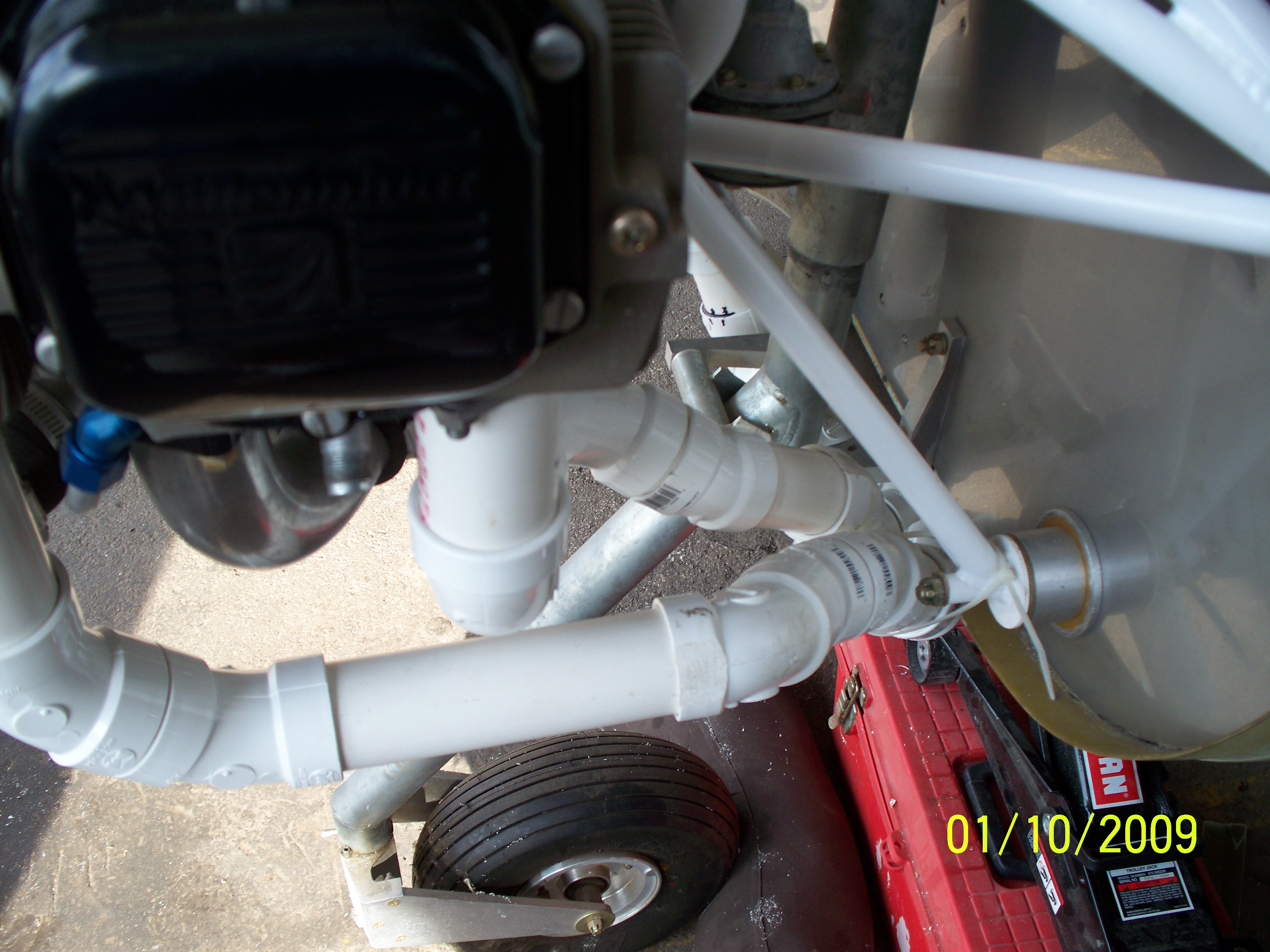
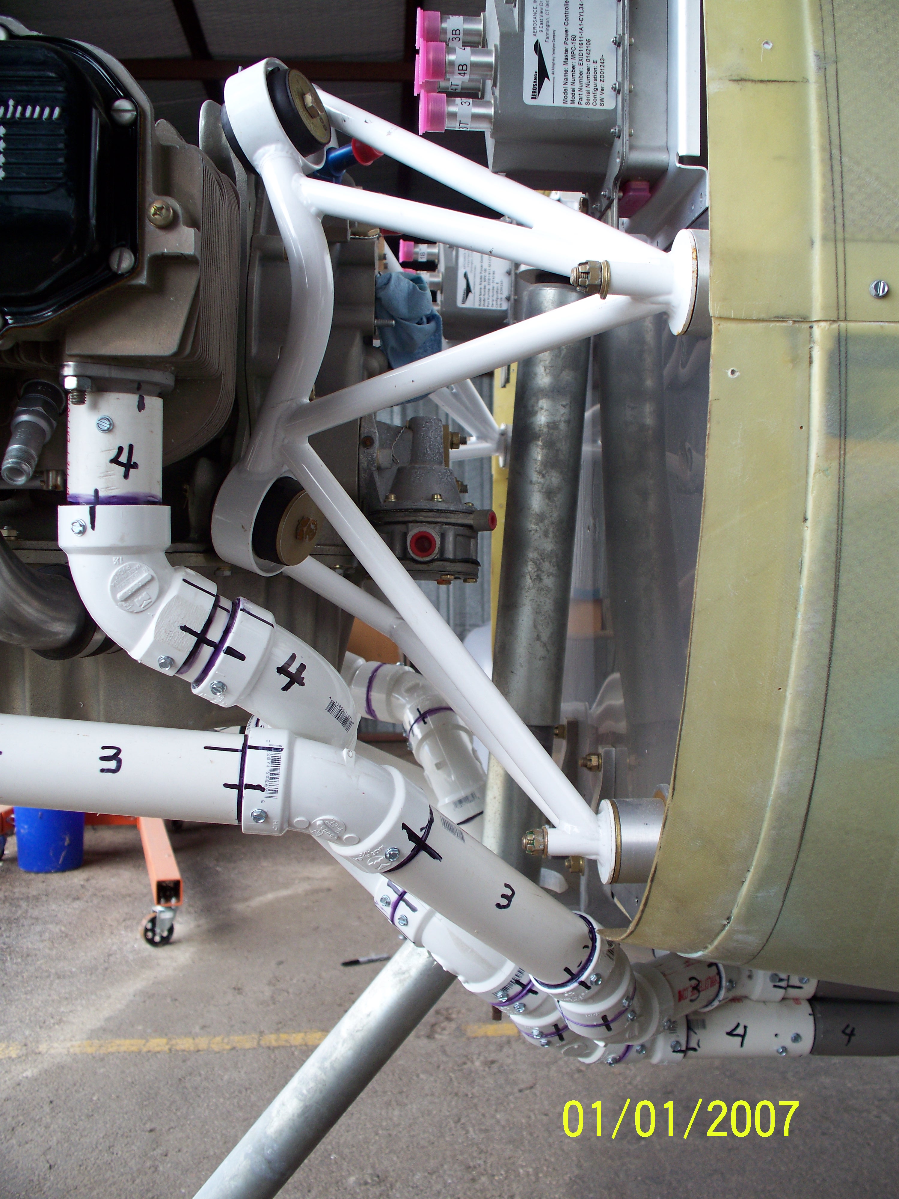
One
big issue I encountered with the exhaust system was how to lock the
four-into-one section on to the four individual exhaust pipes.
The section slides onto the four pipes but didn't seem to go all the
way on and nothing I could do would slide it on farther. Each
pipe goes in about an inch but I thought it could go on farther.
Another problem was how to support the weight of the pipes and still
allow movement with the engine. My final solution to both
problems was a rather odd bracket and strap system that connects to the
fuselage at two points with thick rubber straps to a bracket attached
to the rear of the pipe. The idea is to both support the pipe and
keep it from sliding backwards.
|