Tri-R Technologies
TR-4
BUILDER'S
MANUAL
This Builder's Manual is NOT the official manual
as published by TRI-R Technologies.
RUDDER
ASSEMBLY
Quick Links to Aileron Assembly Sub-Sections:
PREPARATION
SPAR HARD
POINT
RIGHT SIDE
ASSEMBLY
FINAL BONDING
RIGHT SIDE HALF
TEST FIT
FINAL CLOSE
OUT BONDING
FRONT SPAR GLASSING
BALANCING
PREPARATION
The four place rudder assembly is quite similar to the elevator or aileron
assembly procedures. As with all other assemblies we start by locating and
identifying the component parts. The right and left sides should be easily
identified by visualizing their relative location on the plane. The right
side, which will be used first in the assembly is the one which has the flat
sides with no radius at the hinge line edge. Conversely the left side part
has a leading edge radius to minimize the air capture in the joint.
Figure-125: Rudder componets
 |
-
Remove all peel ply and other debris from the two molded parts. Use caution
to avoid breakage of the thin panels, and also to avoid cutting yourself
on the sharp edges.
-
Sand the edges to remove the sharp edges, and the "flash" material which
may be extending past the molded edges. There is no formal trimming for these
parts, but frequently resin and sometimes glass will extend past the edge
of the desired part perimeter. These areas should be obvious, sand them
away.
-
Locate the marked rudder parts or the patterns for the spar and four partial
rib sections.
-
Carefully cut them out of the supplied pre-preg honeycomb panel material,
with a fine tooth or grit tooth blade with a saber saw or band saw.
-
Drill a 1/8th inch vent hole through the center of each rear rib.
SPAR HARD POINT
-
Identify the spar cut out part and prepare a hard point for the actuator
bracket. Establish, and mark the front face.
-
Mark a line 4 1/2 inches up from the bottom, and cut away a strip of the
face plies about 1 1/4 inch wide centered on this mark. and remove the core
material down to the back face.
-
Insert a strip of 1 1/4 wide 1/4 in. thick phenolic in this cut out with
a slurry of MICRO/FLOX on the back and filling in any edge gap.
-
With the spar on a flat surface cover the phenolic and at least 1/2 inch
overlap on each side with 3 ply BID.
-
After the BID has cured, trim edges and drill mounting holes for the actuator
bracket and spacer located within 1/32 of the right hand edge of the spar.
-
Install K 1000 or similar #10-32 nut plates for the two actuator mounting
bolts. Set spar aside for further assembly
Image-117: Rudder Horn Location
 |
RIGHT SIDE ASSEMBLY
Initial assembly will start with the right side panel.

-
Temporally "tack" the panel (outer face down) on a flat surface with dabs
of bondo or 5 minute epoxy. (Note that the forward counterbalance section
shall not be restrained in the flat position but the centerline of this forward
rib shall be straight with the centerlines of the aft ribs)
-
Place the spar in position with the front face 1 1/4 inch back from the hinge
line edge.
-
Clean up any interference to this fit, and temporarily tape in place.
-
Sand the rear edges of the spar to better fit the skin angles.
Image - 118: Rudder Spar Trim
 |
-
Locate the rear rib sections, and establish positions with the top surface
of the top rear rib lined up with the upper inside corner of the hinge line
edge.
-
The next ribs are 20 and 40 inches down (respectively).
Image - 120: Rudder Spar & Rib Positioning
 |
-
Position the one forward rib section flush with the lower edge of the
counterbalance area. (see sketch) The centerline of this rib section shall
be a straight continuation of the center line of the aft ribs as stated
earlier.
-
Cut a 1 inch diameter hole in this rib (as shown in sketch).
This will be used for filling the counter balance weight.
-
Clean up parts and resolve any "fit up" problems.
-
Locate and mark the bonding area for these parts.
-
Remove parts, clean and roughen about 2 inch wide strips in all bonding areas,
and prepare the faces of the ribs and spar for bonding. (Clean and roughen
areas where the bonding will take place)
-
Inspect the assembly and check for proper alignment of all components. Correct
if required.
Image - 119: Assembly View
 |
FINAL BONDING RIGHT SIDE
HALF
-
Using the ribs to set proper angle, "tack" bond the spar in place with dabs
of 5 min. MICRO inside on the honeycomb edges. Allow to cure.
-
Tape the back side of the spar full length with 1 inch wide 2 ply BID tape.
Do not allow this epoxy to cure before proceeding.
-
"Tack" glue the rear ribs in place with a couple of dabs of a 5 min. MICRO
inside on the honey comb core, pressing the parts into place on the wet tape
on the spar. Allow the temporary bonds to cure.
Image - 120: Rudder Spar & Rib Positioning
|
-
Bond each side of the ribs and the inner side of the spar with 1 inch wide
1 ply BID tape. A very small amount of dry MICRO may be useful to correct
local small gaps, and provide a tiny fillet. Use a short bristle brush to
work out bubbles in the tape and to remove any surplus resin. (Remember weight
added here must be added again in the lead for counter balance).
-
Trim any tape edges protruding above the rib or spar edge when sufficiently
cured (knife trim, grind or both as required).
TEST FIT
Test fit the rudder half against the fuselage tail post area to determine
if any thickness correction is required for the rudder leading edge. Trimming
the spar and ribs can be accomplished at this time but should not be required
unless errors have been encountered in assembly
Image 121: Pre-Close Out View
 |
FINAL CLOSE OUT
BONDING
-
Test fit the left rudder skin, noting any interference or other conflicts.
-
When fit up is satisfactory drill two small holes ( about 1/16 inch or less)
near the top and bottom trailing edges of both skins to allow quick and positive
positioning with small nails or pins for the bonding operation.
-
Locate, mark, and prepare areas for bonding on the inner surface of the left
skin.
-
Lay a 1 ply 1 inch wide tape of BID centered on all of the rib and spar bonding
areas. (do not allow to cure)
-
Crush the honeycomb edges back slightly with a strong thumbnail or dull tool
and "stack" a 1/4 inch high wedge of dry MICRO/FLOX along all the exposed
edges
-
Apply a similar "bead" ( about a 1/4 inch wedge) of dry MICRO/FLOX along
the trailing edge of the skin mounted to the flat surface. (Remember weight
added here is going to be doubled in the counter balance)
-
Lay the left skin in place without sliding. Use the pins at the trailing
edge for alignment and sort of "hinge" the skin down in place.
-
Weight the skin enthusiastically in the spar, rib, and trailing edge bond
line areas, but not in the unsupported panel areas. Long skinny sand bags
are recommended, and possibly a straight edge along the trailing edge.
( THE ASSEMBLY WILL BECOME VERY RIGID AFTER THIS OPERATION SO IT IS VERY
IMPORTANT THAT NO TWIST OR BENDING IS INTRODUCED IN THIS OPERATION)
FRONT SPAR
GLASSING
-
Measure the width of BID required to wrap as a "U" channel from flush with
the hinge line to at least 1 inch overlap on the left skin inner surface,
and make a rough pattern of this shape.
-
Prepare a 3 ply BID tape to the pattern for this "U" lamination the length
of the hinge line.
-
Laminate the face of the spar with the "U" shape with the overlap specified..
Bond this tape in place with one edge flush with or slightly extending past
the forward edge of the hinge line.
-
Cut two additional 10 inch lengths, about 2 inches wide, of this 3 ply BID
, and bond in centered on the hinge locations (one inch beyond each end of
the 8 inch hinge sections)
-
Trim the forward edge flush with the molded part, and cut this edge back
1/16 inch for 8 inches at each of the hinge locations (ref. sketch)
-
Test fit to the hinge locations on the fuselage rudder hinge line and drill
hinge mounting holes for both sides of both hinges, coordinated to both parts.
Use temporary bolts and check for unobscured travel
-
Clean and sand the recessed areas at the top and bottom of the rudder. Tape
the skins together in the recessed area with 2 ply prewetted BID tape, holding
alignment of the parts with a small uniform gap beneath the tape.
Image - 122: Rudder Cap
 |
-
After the tape cures, preliminary filling of gap areas with dry MICRO.
-
Rough sanding should be completed before the balancing step.
-
Mount actuator bracket and spacer as shown on sketches.
-
Verify and resolve any fit or clearance problems.
BALANCING
All control surfaces on the KIS Cruiser are 100 percent balanced, and this
includes the rudder.
-
Cut about a 1 inch diameter hole in the front rib about 4 inches back from
the leading edge if this was not previously accomplished.
Image 121 - Rudder Balance
 |
-
Mount the rudder by the hinges such that it can swing down, and balance it
with loose shot or small fragments of lead in a paper cup set in the balance
area.
-
Wet the lead with epoxy and pour it through the hole and allow it to cure
with the lead down and forward.
-
Do not over balance at this time, it will be easier to add than to remove
lead after curing.
-
When the balance is satisfactory, wet out about a 4 inch square of BID and
poke it into the hole and work it into place as a close out. Or an alternate
to this is to mix up a few ounces of a FLOX slurry and reaching in through
the hole with a brush, coat the surface of the lead to the walls to secure
the mass in place.
-
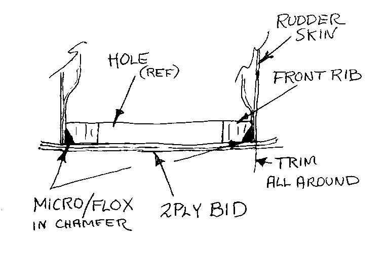
Chamfer the edges of the front rib about 1/8 inch and fill with MICRO/FLOX.
-
Cover the total surface of the rib with 2 ply wet BID allowing it to extend
past the edges.(see figure)
Image - 124: Counter Balance Trimout
 |
-
Trim the overhanging BID
-
Drill a 1/8th inch drain/vent hole in the bottom of the rudder.
The Rudder is Now Complete