Tri-R Technologies
TR-4
BUILDER'S
MANUAL
This Builder's Manual is NOT the official manual
as published by TRI-R Technologies.
AILERON
ASSEMBLY
Quick Links to Aileron Assembly
Sub-Sections:
AILERON ASSEMBLY
PREPARE SPAR
ASSEMBLY
BOTTOM HALF
ASSEMBLY
PREPARE OUTBOARD
END RIB FOR COUNTER WEIGHT
PREPARE FOR THE
AILERON CONTROL BRACKET
BONDING LOWER
SKIN
INSTALL COUNTER BALANCE
TUBE
OUTER SURFACE CLOSE
OUT
ASSEMBLY OF AILERON
COMPONENTS
ACTUATION BRACKET
AILERON ASSEMBLY
The procedures for the four place aileron are very similar to the flap assembly.
One of the primary differences is the fact that the hinge will be on the
upper surface instead of the lower surface as was the case with the flap
assembly.
-
Locate the aileron skins in the kit. There is a top and bottom skin panel
which contain the left and right sides of each flap, connected together in
a single panel.
-
The bottom skins have a slight radius at the forward edge and there is no
difference in the left or right skins in either set at this stage.
-
Clean these and all related parts, stripping off the peel ply and cleaning
away a any loose pieces or other debris.
-
Separate the left from the right by cutting at the center scribe line.
-
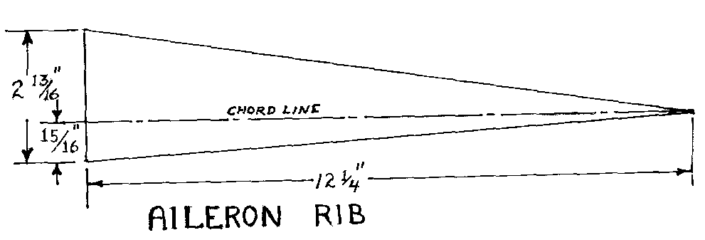
Locate the rib templates and cut the ribs from the supplied honey comb flat
panel material. Each aileron will require two outer (larger) ribs and one
center rib (smaller because of the skin core thickness).
PREPARE SPAR
ASSEMBLY
-
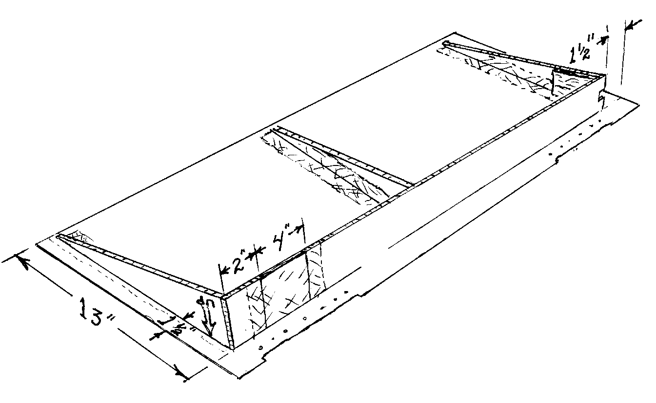
Cut a 4 inch long by 3.1 inch ¼ inch plywood panel. The 4 inch long
by 3.1 inch plywood section is the inboard section of the spar and provides
a "hard point" for the actuation clevise to be installed at a later step.
-
Cut a 36 inch long by 3 inch wide piece of honeycomb material for the leading
edge spar.
-
Mix up a small amount of dry FLOX and butt glue the plywood to the end of
the honey comb section.
-
Apply a two ply bid over the plywood overlapping the panel material by one
inch.
-
Perform this operation on a piece of plastic or waxed paper on a flat surface
and turn over to glass the opposite face in the same manner. Allow at least
an overnight cure.
-
Trim away a any surplus glass and proceed with the aileron assembly.
BOTTOM HALF
ASSEMBLY
-
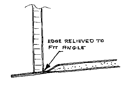
Prepare a flat surface for the aileron assembly and temporarily "tack bond"
the upper aileron skin outer (flat) face to the table surface.
-
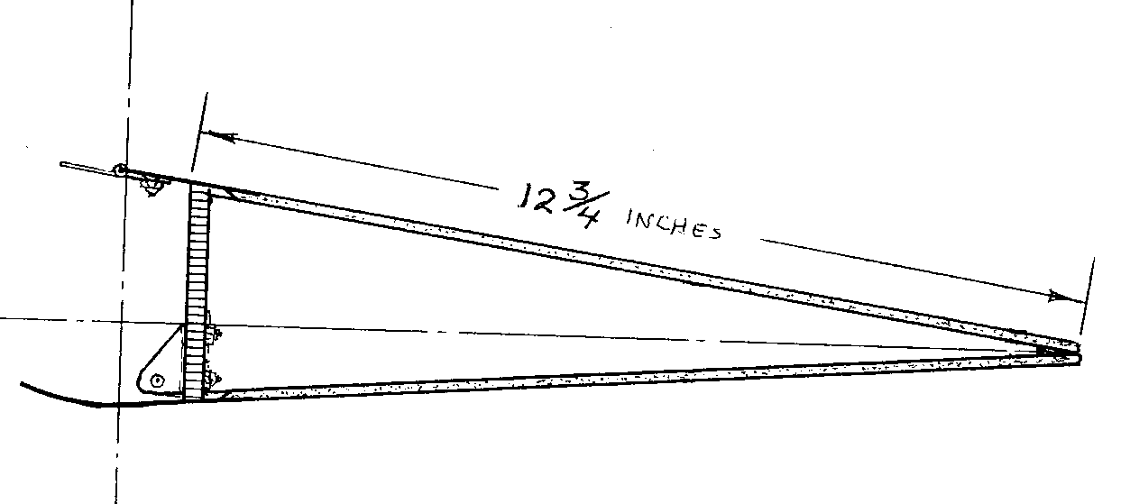
Do a trial assembly as shown in the sketch.
-
Bevel the bottom edge of the spar assembly such that it will fit at the proper
angle established by the ribs.
PREPARE
OUTBOARD END RIB FOR COUNTER WEIGHT
-
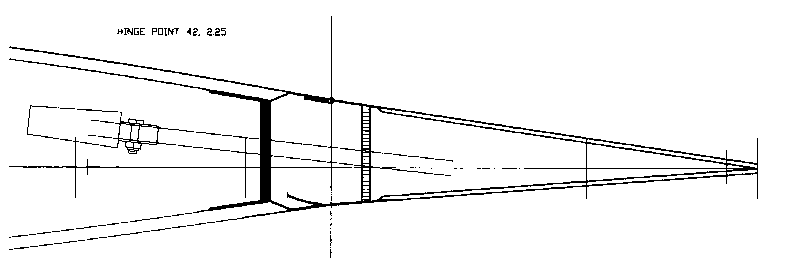
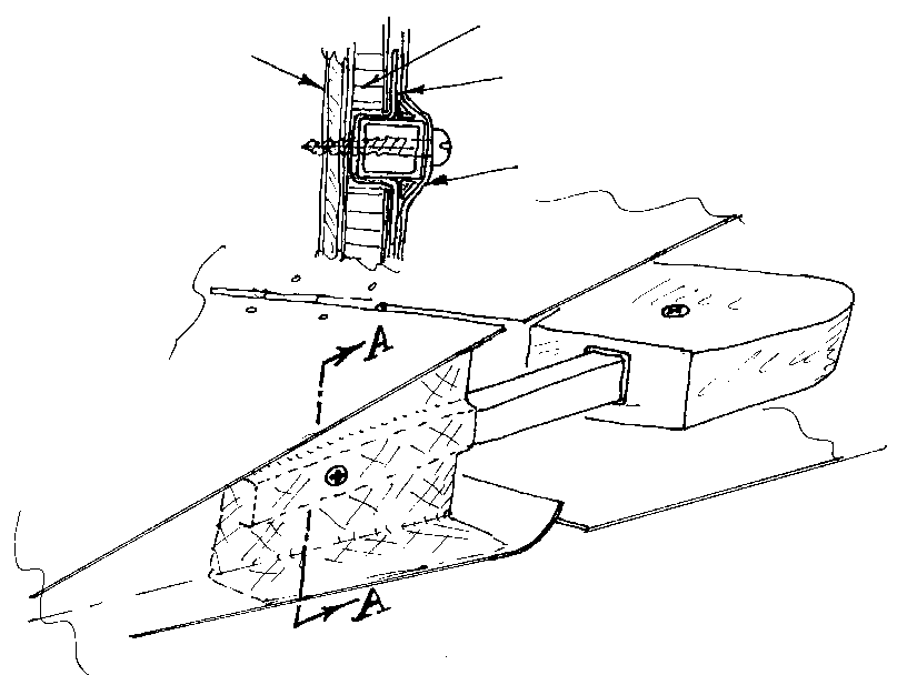
Cut a 11 inch long section of the 1/2 by 1/2 inch square steel tube and clean
and roughen about 3 inches of one end with coarse sand paper.
-
Lay the square tube in position on the outer surface of the outer rib,
overlapping about 2 1/2 inches on the centerline of the rib section ( or
just a couple of degrees upward since aileron travel will be more upward
than downward for classic differential). Draw the outline on the rib.
-
Cut back the outer skin and clear away the core material in an area about
1/16 wider than the tube.
-
Bond a piece of 1/4 inch plywood about 3 inches long and about 2 inches wide
on the back side of the rib to back up this groove.
-
Relieve the edges of these dimensions if required by the rib shape and bond
in place with thick MICRO.
-
Test fit the rib in place in the top half assembly and notch the end of the
spar to also clear the tube when it is installed in a later step.
-
Note the areas where the bonding will take place and roughen with coarse
sandpaper before bonding the
assembly.
-
Tack bond ribs and spar in place and fillet with dry MICRO.
-
Tape both sides of the inner rib and the insides of the outer ribs and spar
with 2 inch 2 ply BID tape.
-
Trim any overhang when the epoxy cures to the rubbery stage
PREPARE
FOR THE AILERON CONTROL BRACKET
-
This is a good time to test fit the aileron with the wing assembly. Remove
the assembly from the table and hold the lower skill in place (tape with
masking tape if that helps) and temporally install the tube and weight.
-
Place the aileron assembly into position in the wing trailing edge channel
where it will be hinged.
The thickness of the aileron should not be too great to allow free movement
without interference with the wing structure. If the aileron is too thick
disassemble and sand away some of the height of the ribs and spar until the
thickness is correct.
-
Position the aileron in the correct location on the wing, and note and mark
the location of the actuator bracket (KS-4) which should be about 2 1/2 inches
from the inboard edge of the aileron skin. Also note and mark the location
of the hinges.
-
Replace the aileron assembly on the flat assembly surface.
-
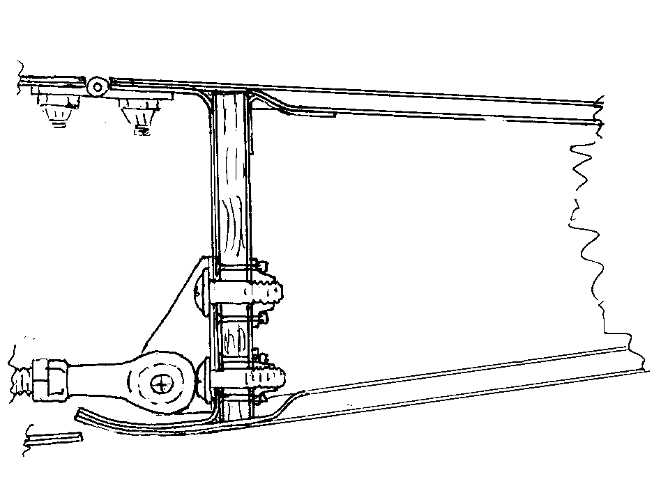
Position the actuator bracket to line up with the marked location of actuation
push rod in the wing and about 1/8 inch from the upper edge of the spar (see
figure).
-
Drill the holes and install the K 1000 -1032A anchor nuts in the proper position
for later permanent installation.
-
Lay the lower skin in position on the bottom half assembly and carefully
inspect the ribs and spars for fit. Rework any high spots noted by sanding
down the offending surface. Make as many trial assemblies as is required
to get a good fit. Note areas for bonding and roughen about a 2 inch wide
path in any of these areas.
BONDING LOWER SKIN
-
Push down the open edge of the honeycomb on the ribs and spar about 1/8 inch.
-
Pile a dry MICRO/FLOX mixture in a bead about 1/4 inch higher than the edges
of the ribs and spar.
-
Wet out the surfaces prepared for bonding with some standard epoxy mix.
-
Lay a bead of dry FLOX where the two trailing edges will join.
-
Lower the bottom skin carefully into place and verify squeeze out of adhesive
in all the critical areas.
-
Use some paper tape to hold the skill in position, and weight down securely
in all the areas being bonded. Clean up excess adhesive for future glassing.
INSTALL COUNTER
BALANCE TUBE
-
After the lower skin bond has cured, bond the counter balance steel square
tube in place by pre filling the cut out groove edges in the outer rib with
dry Micro and pressing one layer of pre wetted bid into the groove under
the tube.
-
Size this cloth for about 3/4 to 1 inch wide on either side of the tube.
Trim as required so as to not overlap to the upper or lower skins. The upper
surface glass cover will be accomplished in the next step.
OUTER SURFACE CLOSE
OUT
-
Prepare the outer surfaces for final close out bonding. Roughen and clean
all bond areas, remember to fillet any sharp inside comers with dry
MICRO.
-
The steel tube comers should also be filleted with dry MICRO.
-
Apply two ply BID to all outer surfaces of ribs and spar with a full overlap
of all the overhanging edges of the aileron skins.
-
Locate the hinge areas and add a four layer BID prelam 3 inches wide and
10 inches long in each of the two hinge areas on each aileron. Lap at least
I inch up onto the spar surface over the ten inch length.
-
When the layers are cured and knife trimmed, drill one or two holes through
the glass covering and the steel tube and assure against any axial shifting
with pop rivets or sheet metal screws. (sheet metal screws are preferred)
ASSEMBLY OF
AILERON COMPONENTS
-
Trim the glass away from the mounting holes for the aileron actuation mounting
bracket (or drill out with 3/16 drill - do not damage threads in the anchor
nuts).
-
Install the actuator bracket (KS-4) with supplied hardware.
ACTUATION BRACKET
-
In the hinge areas, trim about a 1/16 recess for the bead of the hinge.
-
Align the aileron with the wing trailing edge in its final position.
-
Drill the hinge screw holes and install the hinges with MS24694-S5 counter
sunk machine screws, AS 135-017 Tinnerman washers, and either lock nuts or
appropriate anchor nuts.
-
Either mount the aileron to the wing or via another support and position
the aileron weight on the 1/2 inch square tube.
-
Locate the balance point and assure adequate aileron free travel.
-
Drill a 3/16 hole through the weight and mounting tube and secure with a
10-32 bolt and self locking nut.
The aileron may be installed to the wing.


